





EDFA Applications: Booster, In-Line and Pre-Amp Deployment Guide
 Jul 02, 2026|
 In real EDFA applications, the amplifier decision is not just about making a weak optical signal stronger. In a DWDM, metro, DCI, CATV or long-haul link, the more important question is where the EDFA should sit, how much gain it should provide, what noise figure you can tolerate, and what can go wrong after the system goes live.
Fiber optic amplification is useful because it can extend an optical link without converting every wavelength into an electrical signal and back again. But the wrong EDFA position may still "work" during a lab power test while creating poor OSNR, gain tilt, transient spikes, connector burns or unstable receiver margins after channels are added, dropped or protected.
This article does not repeat the full EDFA working principle. If you need the basic comparison between EDFA, Raman and SOA first, see our guide to optical amplifier types for DWDM systems. Here, we focus on deployment decisions: which EDFA configuration fits which link, what parameters matter in sourcing, and which field risks are usually missing from standard datasheets.
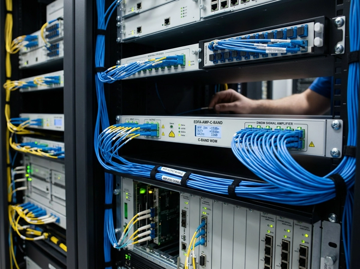
Start With the Span Problem, Not the Amplifier Name
A reliable EDFA decision starts from the span loss, not from the amplifier label. A 100 km single-mode route at around 0.2 dB/km already consumes about 20 dB before connector loss, patch panels, MUX/DEMUX insertion loss, dispersion compensation, aging margin and repair margin are added. In practice, once total planned loss moves toward 25–30 dB, we normally stop treating EDFA as an optional accessory and start checking whether booster, in-line or pre-amplifier placement is needed.
An EDFA is attractive because it supports optical signal amplification without OEO regeneration. Instead of converting every wavelength into an electrical signal and back again, one optical amplifier can raise a whole C-band channel group, which is why EDFA applications became central to WDM and DWDM transport.
But this conclusion only holds when the original signal still has usable OSNR. An EDFA does not fix dispersion, dirty connectors, poor launch power planning, bad channel balancing or receiver mismatch. It gives the link more optical power and changes the OSNR profile. Whether that helps or hurts depends on where the amplifier is installed and how close the system already is to the noise floor.
Our practical position is clear: for B2B DWDM sourcing, "high gain" is not automatically better. A correctly placed 17–23 dB EDFA with controlled output power and a suitable noise figure is usually more valuable than an oversized amplifier that pushes the link toward nonlinear effects, gain tilt or safety risk.
Booster, In-Line or Pre-Amp: The Deployment Logic
The simplest EDFA applications map has three positions, but each one solves a different problem. Treating them as interchangeable is one of the common mistakes in long-span DWDM planning.
| EDFA position | Where it sits | Main job | Typical priority | Common mistake |
|---|---|---|---|---|
| Booster EDFA | After transmitter, transponder, MUX or switch output | Raises launch power into the fiber span | High output power, stable gain, flatness across channels | Using too much launch power and creating nonlinear penalties |
| In-line EDFA | Between two fiber spans or at an intermediate site | Compensates span loss before the signal falls too close to the noise floor | Balanced gain, low noise figure, remote monitoring | Placing it too late, then amplifying noise with the weak signal |
| Pre-amplifier EDFA | Before receiver, DEMUX or coherent receiver input | Lifts weak signals before detection | Low noise figure, receiver sensitivity support | Expecting a pre-amp to fix a poor OSNR that was already lost upstream |
A booster EDFA is normally used when the transmitter-side signal has already lost power through passive components. In a DWDM system, the MUX alone can consume several dB, and the combined channel group must enter the fiber with enough power to survive the first span. A booster EDFA for DWDM usually needs high output power and good gain flatness, while ultra-low noise is less critical than in a receive-side amplifier because the input signal is still relatively strong.
An in-line EDFA is used when the route is too lossy for end-point amplification alone. As a field rule, 80–100 km spans often need an in-line check, and the threshold moves earlier if MUX/DEMUX insertion loss, OADM pass-through loss, splice count or old patching already consumes 5 dB or more before fiber attenuation is fully counted. The exact point still needs a link map, but the default judgment should not be "it depends." It should be: calculate in-line placement before the signal falls too close to the noise floor.
A pre-amplifier EDFA sits near the receiving side and is chosen for low noise figure. Its job is not to "make everything powerful." Its job is to lift a weak but still usable optical signal before receiver detection. This is why 980 nm pumping is often preferred in low-noise EDFA designs. RP Photonics notes that EDFAs commonly use pump wavelengths around 980 nm and 1480 nm, with 980 nm pumping often associated with low-noise operation in pre-amplifier designs (RP Photonics).

The decision can reverse in edge cases. If an 80 km route loses most of its margin at the transmitter side because of a passive MUX, a booster may solve the main budget problem. If the same route arrives weak after DEMUX loss, a pre-amp may matter more. If total span loss pushes beyond about 25–30 dB, relying only on a far-end pre-amp is often too late because OSNR may already be damaged upstream. That is why we ask for the full fiber loss, passive loss and receiver threshold before recommending a booster, in-line EDFA or pre-amplifier EDFA.
For deeper comparison of EDFA, SOA and Raman behavior under different system constraints, you can also review our EDFA, SOA and Raman optical amplifier comparison.
EDFA Applications by Real Network Scenario
EDFA applications look different in a submarine backbone, a metro DWDM ring, a CATV distribution network and a 5G backhaul route. The amplifier principle is similar, but the deployment risk is not.
Submarine EDFA for Long-Haul DWDM Links
In submarine and long-haul systems, the hard number matters. Repeatered subsea designs may evaluate optical amplification around 50–100 km span intervals, but the exact spacing depends on fiber loss, capacity target, power feed limits, repeater design and system margin. ITU-T submarine cable design guidance also discusses redundant pump-laser configurations and 25-year lifetime reliability calculations for submarine repeaters, which is why submarine EDFA decisions are less about simple gain and more about long-term reliability (ITU-T G.Suppl.41).
For terrestrial long-haul links, intermediate amplifier sites are easier to access, but spacing is still constrained by huts, power, fiber route rights and protection design. The useful rule is this: long-haul EDFA planning should protect OSNR before it collapses, not after. If an amplifier is added only after the signal becomes too weak, it raises both the signal and accumulated noise. That is why in-line EDFA placement is a link-design decision, not a purchasing afterthought.
Metro EDFA for DWDM Rings and Regional Networks
A 40 km metro DWDM ring may still need amplification if passive components eat the budget before the fiber does. ROADMs, OADMs, patch panels, MUX/DEMUX modules and aging connectors can consume enough margin that distance alone becomes a misleading indicator.
This is where many metro EDFA applications become more subtle. In a clean point-to-point span, the EDFA decision may look easy. In a ring with add/drop nodes and protection switching, channel loading changes more often, and the amplifier must remain stable when wavelengths are added, removed or rerouted.
EDFA for DCI and 40–120 km Campus Links
DCI projects usually care about predictable deployment, compact form factor, fast delivery and compatibility with 100G, 200G, 400G or higher-rate optics. For 40–120 km DCI or campus-to-campus transport, a typical EDFA application is to extend the link power budget of a DWDM or OTN system without building a full regeneration site.
CATV EDFA Amplifier Deployment
A CATV EDFA amplifier is often judged first by output power, but the failure point is often the connector, not the amplifier chassis. High-power downstream distribution may feed multiple optical nodes from one headend, so output per port, port balance, connector cleaning and reflection control matter as much as total dBm.
A CATV EDFA should be evaluated for output power, port count, flatness, carrier-to-noise impact, and stability across the operating wavelength range. The wrong choice is to focus only on total output power while ignoring per-port balance and connector cleanliness.
5G Backhaul EDFA for Access Aggregation
In 5G backhaul, the default assumption should not be "use the strongest booster." Loss is often concentrated around passive distribution, cabinet patching and receiver-side access aggregation, so compact pre-amplifier EDFA or moderate booster EDFA placement is often more practical than a high-power unit pushed into every route.
L-Band EDFA for Capacity Expansion
When a C-band system approaches its channel capacity, operators may evaluate L-band expansion or hybrid amplification designs. EDFA can support C-band and L-band variants, but the gain profile, noise behavior and amplifier design are not identical.
The Pitfalls Nobody Puts in the Datasheet
High-power EDFA deployment has a safety and reliability side that many product pages skip. This is not just legal caution. It affects connector life, field maintenance, service stability and equipment protection.

The first risk is fiber fuse. RP Photonics describes fiber fuse as a destructive effect where hot plasma propagates back through the fiber core and can occur in standard single-mode fiber at surprisingly low power levels, sometimes below 1 W. It also notes that high-power fiber amplifiers are particularly at risk and need appropriate reliability measures (RP Photonics).
The second risk is connector end-face contamination. MicroCare explains that high-power lasers can damage fiber networks when contamination on the fiber end face absorbs optical energy, converts it into heat, and damages the glass; it also notes that damage may extend beyond the connector area into the fiber (MicroCare).
How to Spec and Source the Right EDFA
A good erbium-doped fiber amplifier specification should be written from the link backward. Start with the span target, passive loss, fiber type, channel plan, transceiver type, receiver threshold and OSNR requirement. Then define the amplifier position.
| Specification item | Why it matters in EDFA applications |
|---|---|
| Operating band | Confirms C-band, L-band or extended-band compatibility with the channel plan |
| Gain range | Determines whether the amplifier can compensate actual link loss without overdriving the span |
| Output power | Important for boosters and CATV distribution, but must be balanced against nonlinear and safety risk |
| Noise figure | Critical for pre-amps, in-line locations and long-haul OSNR preservation |
| Gain flatness | Prevents wavelength imbalance in multi-channel DWDM systems |
| Input power range | Ensures stable operation under realistic channel loading |
| Control mode | AGC, APC or other modes affect live channel changes and transient behavior |
| Safety functions | Pump shutdown, alarms and power reduction protect people, connectors and equipment |
| Management interface | SNMP, web, serial or other interfaces help NOC teams monitor amplifier health |
| Environmental design | Cooling, power redundancy and temperature alarms affect long-term stability |
For B2B procurement, the red flag is not a low price by itself. The red flag is a supplier who cannot explain why the EDFA should be a booster, in-line unit or pre-amplifier for your exact route. If the answer is only "higher output power is safer," the proposal is not ready for approval.
FB-LINK has manufactured optical modules since 2008 and supports DWDM, DCI and long-span optical projects with a 1600㎡ clean production environment, 200+ staff, ROHS-compliant processes and experience serving 180+ customers. In EDFA sourcing, the useful part of that background is not the company size alone; it is the ability to review optical modules, MUX/DEMUX loss, DCI/OTN span targets and amplifier placement together rather than quoting each item in isolation.
If you are planning an 80 km, 120 km or custom DWDM span, send the fiber loss, MUX/DEMUX loss, wavelength count and transceiver type. We can help match booster, in-line or pre-amplifier configurations from our EDFA optical amplifier product range so the unit is not oversized, under-specified or placed where it cannot protect OSNR.
FAQ
Q: What are the main applications of an EDFA?
A: EDFA is mainly used in long-haul DWDM, submarine links, metro rings, CATV distribution, DCI and 5G backhaul where optical power must be boosted without OEO regeneration.
Q: What is the difference between booster, in-line and pre-amplifier EDFA?
A: A booster EDFA raises launch power after the transmitter, an in-line EDFA compensates span loss mid-link, and a pre-amplifier EDFA lifts weak signals before the receiver.
Q: Why use EDFA for fiber optic amplification instead of regenerators?
A: EDFA amplifies light directly and can support many DWDM wavelengths together, reducing site count, latency and cost compared with wavelength-by-wavelength regeneration.
Q: What causes gain tilt and transients in EDFA links?
A: Gain tilt and transients are caused by wavelength-dependent gain, channel loading changes, pump dynamics and add/drop events that disturb surviving-channel power.
Q: Are high-power EDFA deployments a safety risk?
A: Yes, high-power EDFA links can create fiber fuse, connector end-face burns and eye-safety risks if power control, connector cleaning and shutdown procedures are not handled correctly.