





Optical Link Module Works in Telecom Systems
 Oct 31, 2025|
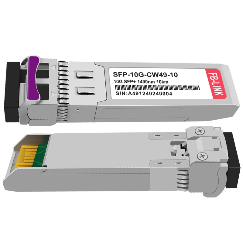
An optical link module converts electrical signals from network equipment into optical signals that travel through fiber optic cables, then converts them back to electrical signals at the receiving end. In telecom systems, these modules enable high-speed data transmission across distances ranging from meters to over 100 kilometers, supporting everything from 5G networks to data center interconnections.
Core Components and Signal Conversion Process
The optical link module consists of two primary functional units that work in tandem to facilitate bidirectional communication. The transmitter section houses a laser diode or LED that converts incoming electrical signals into modulated light pulses. Modern telecom applications predominantly use laser diodes operating at specific wavelengths-typically 850nm for short-reach multimode applications, and 1310nm or 1550nm for long-reach single-mode deployments.
The conversion process begins when electrical signals from network switches or routers arrive at the module's electrical interface. The transmitter's driver circuit modulates the laser diode, creating light pulses that represent digital data. This optical signal then propagates through fiber optic cable at approximately 200,000 kilometers per second-about two-thirds the speed of light in vacuum.
At the receiving end, a photodetector (usually a PIN photodiode or avalanche photodiode) captures the incoming light pulses and converts them back into electrical current. A trans-impedance amplifier then boosts this signal and converts it to a voltage that downstream circuitry can process. The entire conversion cycle-from electrical to optical and back-introduces latency measured in nanoseconds, making optical link modules suitable for latency-sensitive telecom applications.
The module housing provides both mechanical support and thermal management. Heat dissipation becomes particularly critical in high-speed modules operating at 400G or 800G, where power consumption can exceed 12-15 watts. Advanced modules incorporate integrated thermal monitoring via Digital Optical Monitoring (DOM) capabilities, allowing network operators to track temperature, optical power levels, and other performance metrics in real-time.
Wavelength Division and Multi-Channel Operation
Telecom systems leverage wavelength division multiplexing (WDM) to maximize fiber capacity. Coarse WDM (CWDM) modules operate on a grid of 20nm spacing, supporting 8-18 channels per fiber. Dense WDM (DWDM) tightens this to 0.8nm (100 GHz) or 0.4nm (50 GHz) spacing, enabling 40-96 channels on a single fiber strand. This spectral efficiency proves essential for metro and long-haul telecom networks where fiber availability is constrained.
Each wavelength channel operates independently, carrying its own data stream. A 100G DWDM module transmitting at 1550.12nm can coexist with dozens of other modules on the same fiber, each at its designated wavelength. This parallel transmission architecture supports aggregate capacities exceeding 10 terabits per second on a single fiber pair-sufficient to handle traffic from thousands of simultaneous users.
The ITU-T G.694.1 standard defines the DWDM wavelength grid used in telecom systems. Modules must maintain wavelength stability within ±2.5 GHz under operating temperature variations from -5°C to +70°C for indoor applications, or -40°C to +85°C for outdoor deployments. Temperature-controlled lasers with integrated thermoelectric coolers (TECs) help maintain this precision in demanding environments.
Application Architecture in 5G Networks
The 5G network architecture creates three distinct deployment scenarios for optical link modules, each with specific technical requirements. Fronthaul connections link the radio unit (RU) to the distributed unit (DU), typically requiring 25G SFP28 modules that support eCPRI protocol. These connections demand deterministic latency below 100 microseconds and operate over distances of 10-20 kilometers in urban deployments.
Data from industry deployments shows that 25G modules now account for approximately 32% of optical transceiver shipments in 5G infrastructure. The shift from 10G to 25G fronthaul represents a bandwidth multiplication factor of 2.5x, essential for supporting the cell densification required in 5G networks. Network operators deploy these modules in outdoor environments where temperature extremes and humidity require industrial-grade specifications.
Midhaul connects the DU to the centralized unit (CU), aggregating traffic from multiple cell sites. This segment increasingly adopts 100G and 200G coherent modules capable of 40-80 kilometer reaches without optical amplification. The use of coherent detection technology enables higher spectral efficiency and improved noise tolerance compared to direct-detect systems.
Backhaul provides the final connection from CU to the core network, where 400G QSFP-DD and 800G OSFP modules are gaining traction. Market research indicates that 400G module shipments exceeded 3 million units in the first quarter of 2024, with approximately 15-20% allocated to telecom backhaul applications. The transition to 400G+ backhaul supports the aggregate bandwidth requirements of densified 5G networks in metropolitan areas.

Form Factors and Interface Standards
The physical packaging of optical modules follows industry-standard multi-source agreements (MSAs) that ensure interoperability across equipment vendors. Small form-factor pluggable (SFP) modules measure 8.5mm × 13.4mm × 56.5mm and support data rates up to 25Gbps. The hot-pluggable design allows network operators to upgrade or replace modules without powering down the host system-a critical capability for maintaining carrier-grade network availability.
Quad SFP (QSFP) modules quadruple the port density by packing four channels into a single package. QSFP28 supports 100G through 4×25G electrical lanes, while QSFP-DD (double density) doubles this to 8 lanes for 400G operation. The OSFP form factor provides enhanced thermal management for 800G modules, with a footprint of 22.58mm × 107.5mm compared to QSFP-DD's 18.35mm × 89.4mm.
The electrical interface between module and host follows standards defined by the Optical Internetworking Forum (OIF) and IEEE. The Common Electrical Interface (CEI) specification defines signaling characteristics for 25G and 50G lanes. Modern modules implement Forward Error Correction (FEC) algorithms-typically Reed-Solomon RS(544,514) or KP4 FEC-to improve bit error rates to 10^-15 or better, even when the raw optical signal BER reaches 10^-4.
Power Budgets and Link Performance
Optical power budget calculations determine the maximum transmission distance for a given module and fiber type. A 10GBASE-LR module typically provides -1 to +1 dBm transmit power and -14.4 dBm minimum receive sensitivity, yielding a 15.4 dB power budget. Subtracting fiber attenuation (0.4 dB/km at 1310nm), connector losses (0.5 dB each), and margin (3 dB), the module supports approximately 25-28 kilometer links.
Long-reach applications require higher transmit power and better receive sensitivity. Extended range (ER) modules deliver +4 to +7 dBm output with -18 dBm sensitivity, extending reach to 40 kilometers. Zettabyte-reach (ZR) coherent modules achieve 80-120 kilometer spans by employing advanced modulation formats like dual-polarization quadrature phase shift keying (DP-QPSK) combined with digital signal processing.
Chromatic dispersion limits transmission distance for high-speed direct-detect systems. At 25Gbps, dispersion restricts standard modules to 10-15 kilometers on single-mode fiber. Precision OT's Genesee ASIC technology addresses this through electronic dispersion compensation, extending 25G links to 40+ kilometers without external dispersion compensation modules. This innovation reduces deployment costs in 5G fronthaul networks by eliminating the need for additional amplification equipment.
Diagnostic and Management Capabilities
Modern optical modules implement the Common Management Interface Specification (CMIS) defined by SFF Committee standards. CMIS provides a standardized register interface for reading module temperature, supply voltage, transmit/receive power, and alarm/warning thresholds. This telemetry enables proactive network management through integration with software-defined networking (SDN) controllers.
Real-time optical power monitoring serves multiple purposes in telecom operations. Gradual degradation in received power indicates fiber degradation, dirty connectors, or impending laser failure. Sudden changes trigger protection switching in redundant network configurations. Some advanced modules support automatic power adjustment, optimizing transmit power based on measured receive levels to minimize power consumption.
The module's EEPROM stores manufacturing data including part number, serial number, date code, and vendor-specific calibration parameters. Telecom operators use this information for inventory management, failure analysis, and compliance verification. The Small Form Factor (SFF) Committee maintains these standards through documents SFF-8024, SFF-8636, and others that define memory map layouts and compliance requirements.
Emerging Technologies and Future Directions
Silicon photonics integration represents a significant shift in optical module manufacturing. By fabricating optical components on standard CMOS silicon wafers, manufacturers reduce costs while improving performance. Industry analysts project silicon photonics modules will capture 20-30% of the 800G market by 2025, growing from approximately 1 million units in late 2024.
Co-packaged optics (CPO) takes integration further by mounting optical dies directly alongside switch ASICs within the same package. This architecture eliminates SerDes power consumption and reduces latency by removing the electrical interface between switch and optics. Early CPO demonstrations showed 30-40% reduction in total power consumption compared to pluggable modules at 51.2 Tbps switch capacities.
Linear pluggable optics (LPO) removes digital signal processing and clock recovery circuits from the module, relying on the host switch to handle these functions. LPO modules consume approximately 40% less power than conventional modules-around 7-8 watts for 800G versus 12-14 watts. Market adoption remains limited to specific hyperscale data center applications, but telecom carriers are evaluating LPO for energy-constrained cell site deployments.
The transition to 1.6 terabit modules began in late 2024 with field trials by major cloud providers. These modules use 8×200G electrical lanes and advanced modulation techniques to double 800G capacity. Telecom backhaul networks will likely adopt 1.6T modules in 2026-2027 as aggregation demands increase with expanded 5G coverage and growing traffic per subscriber.
Reliability and Environmental Considerations
Telecom-grade optical modules must operate reliably for 10-20 years under continuous operation. Mean time between failures (MTBF) typically exceeds 500,000 hours at 40°C. Component selection focuses on established reliability: hermetically sealed TO-can packages protect laser diodes from moisture and contamination, while qualified vendors demonstrate less than 100 FIT (failures in time per billion device-hours).
Environmental testing validates operation across temperature, humidity, and mechanical stress ranges. Modules destined for outdoor 5G deployments undergo testing at -40°C to +85°C, with humidity up to 85% relative humidity non-condensing. Vibration testing per GR-63-CORE ensures modules withstand transportation shock and cell tower oscillation. Salt spray testing validates corrosion resistance for coastal installations.
Power efficiency considerations drive module design as telecom operators face rising electricity costs. A cell site with 24×25G fronthaul modules consuming 1.2 watts each draws 28.8 watts continuously-over 250 kilowatt-hours annually per site. Multiplied across thousands of cell sites, even small efficiency improvements yield substantial operational cost reductions and carbon footprint benefits.
Deployment Considerations for Network Operators
Selecting appropriate optical modules requires balancing technical specifications against operational requirements. Single-mode modules cost more than multimode but support longer distances-critical for cell site connectivity where fiber routes may exceed 10-20 kilometers. The 25G modules used in 5G fronthaul typically price at $150-300 depending on reach and features, while 100G coherent modules for backhaul range from $800-2000.
Inventory management complexity increases with module diversity. A metropolitan telecom network might deploy 10-15 different module types across various applications. Standardizing on compatible platforms and maintaining adequate spares inventory ensures rapid service restoration after failures. Many operators establish relationships with third-party compatible module vendors to supplement OEM supplies and reduce costs by 30-50%.
Testing and qualification procedures verify module compatibility before deployment. Optical time-domain reflectometry (OTDR) characterizes fiber plant quality, while bit error rate testing (BERT) validates link performance under load. Telecom operators typically require 24-48 hours of error-free operation at full throughput before accepting new modules for production deployment.
Frequently Asked Questions
What distinguishes single-mode from multimode optical link modules?
Single-mode modules use lasers with narrow spectral width operating at 1310nm or 1550nm wavelengths to transmit through 9-micron core fiber. These support distances from 2 kilometers to over 100 kilometers. Multimode modules typically use 850nm VCSELs transmitting through 50-micron or 62.5-micron fiber, limiting reach to 550 meters but reducing cost. The choice depends on application distance requirements-single-mode for inter-building links and multimode for intra-building connections.
How does chromatic dispersion affect high-speed optical transmission?
Chromatic dispersion causes different wavelengths of light to travel at slightly different speeds through fiber, spreading optical pulses and causing inter-symbol interference. The effect increases with both transmission speed and distance. At 10Gbps, dispersion limits reach to approximately 80 kilometers; at 25Gbps, this drops to 10-15 kilometers without compensation. Advanced modules incorporate electronic dispersion compensation or chirped lasers to mitigate this effect, extending practical reach for 5G fronthaul applications.
What role do optical link modules play in 5G network architecture?
5G networks deploy optical modules across three distinct segments. Fronthaul connections use 10G-25G modules linking radio units to distributed units with sub-100-microsecond latency requirements. Midhaul employs 100G-200G modules aggregating traffic from multiple cell sites to centralized processing units. Backhaul utilizes 400G-800G modules connecting to core networks. This layered architecture supports the bandwidth multiplication required for 5G services while enabling flexible network topologies.
Can different vendors' optical modules be mixed in the same network?
Yes, when modules comply with MSA standards and match electrical/optical specifications. The multi-source agreement framework ensures mechanical and electrical compatibility across vendors. However, operators should verify proper operation through testing, as some advanced features (enhanced DOM, vendor-specific diagnostics) may not interoperate. Many networks mix OEM and compatible third-party modules to balance cost and support considerations, with compatible modules often priced 30-50% below OEM equivalents.
Understanding optical link module functionality in telecom systems requires appreciating both the physical layer signal conversion and the network architecture context. These modules represent the critical interface between electronic switching infrastructure and optical fiber transmission plant, enabling the bandwidth scalability and reach extension that modern telecommunications demands. As 5G deployments expand and traffic per subscriber continues growing, optical module technology will keep evolving to support terabit-scale capacities while maintaining the reliability and efficiency that carrier networks require.
Data Sources:
Cignal AI Optical Components Report (Q1 2024, Q3 2024) - Market shipment data and forecasts
Fortune Business Insights Optical Transceiver Market Report (2024-2032) - Market size and CAGR projections
Lumentum Holdings Inc. OFC 2024 Press Release - Technical specifications for 200G components
Mordor Intelligence Optical Transceiver Market Analysis (2025-2030) - Application segment breakdown
Precedence Research 5G Optical Transceiver Market Report (2025-2034) - 5G deployment statistics
FS Community 5G Network Deployment Guide (August 2024) - Technical architecture details
Heavy Reading IPoDWDM Industry Report (November 2024) - 400ZR/800ZR interoperability demonstrations
Deep Fundamental Substack Optical Module Market Analysis (September 2024) - Silicon photonics adoption forecasts
Grand View Research 5G Optical Transceiver Report (2023-2030) - Cost structure analysis
Precision OT 5G-Advanced Technology Blog (January 2025) - Dispersion compensation technology