





Transceiver fiber optic are manufactured in facilities
 Nov 06, 2025|
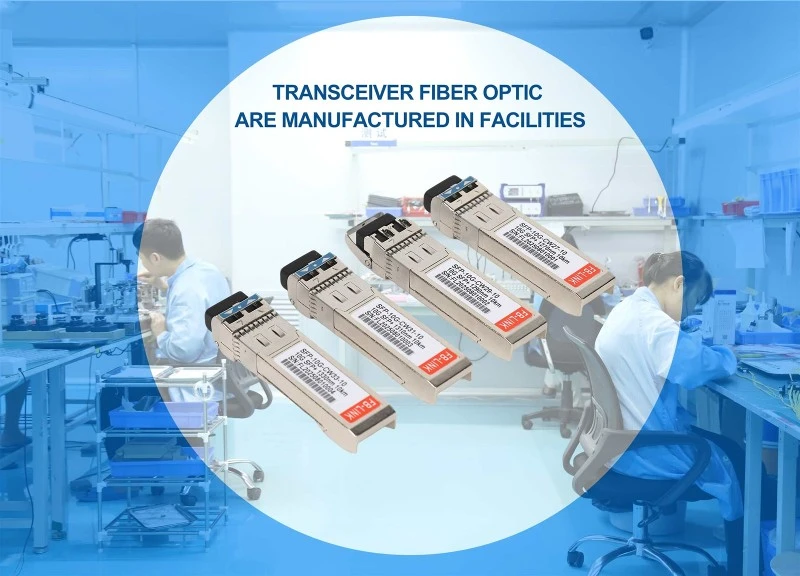
Transceiver fiber optic devices are manufactured in specialized facilities that combine advanced cleanroom environments, precision assembly lines, and rigorous quality control systems. These facilities integrate optoelectronic component production, printed circuit board assembly, and comprehensive testing to produce modules capable of converting electrical signals to optical signals and back.
Manufacturing locations span globally, with major production hubs concentrated in China (Shenzhen, Qingdao, Wuhan), the United States (Silicon Valley, San Jose), Malaysia, and Taiwan. The optical transceiver market reached $12.6 billion in 2024 and continues growing at 13-16% annually, driving facility expansion and technological advancement.
Manufacturing Facility Requirements
Cleanroom Standards and Environment Control
Cleanroom facilities form the foundation of transceiver fiber optic manufacturing. These controlled environments maintain particle counts at ISO Class 5 to ISO Class 7 levels, with Class 5 cleanrooms containing a maximum of 100,000 particles (0.5 microns or larger) per cubic meter of air. For comparison, outdoor urban air contains approximately 35 million particles per cubic meter.
The stringent requirements exist because fiber optic technology transmits data through glass strands thinner than human hair. Even microscopic contamination-as small as 0.5 microns-can cause light transmission loss or signal degradation. A human hair measures 100 microns in diameter, while the particles counted in cleanrooms measure just 0.5 microns, making them invisible to the naked eye.
Temperature and humidity control systems maintain stable conditions between 20-24°C with humidity levels of 40-60%. These parameters prevent thermal expansion of components and moisture-related damage during assembly. Air filtration systems cycle air through HEPA filters every 15-20 minutes, removing particles continuously.
Personnel account for approximately 75% of contamination sources in cleanrooms, with the remaining 25% coming from equipment, ventilation systems, and room structures. Manufacturing staff wear full cleanroom suits, including hoods, masks, gloves, and specialized footwear. Even a motionless person generates 100,000 particles (0.3 microns or larger) simply by sitting or standing.
Advanced Assembly Equipment
Modern transceiver fiber optic facilities house automated assembly lines featuring precision alignment equipment, surface-mount technology (SMT) stations, and reflow soldering systems. Alignment equipment achieves tolerances within micrometers to ensure optimal signal transmission between laser diodes and fiber cores.
Pick-and-place machines position tiny components-including integrated circuits, resistors, and capacitors-onto printed circuit boards with accuracy measured in thousandths of a millimeter. These automated systems can place thousands of components per hour while maintaining consistent quality standards.
Die bonding equipment attaches laser diodes and photodetectors to their housings using specialized adhesives or soldering techniques. Wire bonding machines then create electrical connections between chips and circuit boards using gold or aluminum wires as thin as 25 microns in diameter.
Fiber coupling stations align optical fibers with laser sources or photodetectors, a critical process requiring sub-micron precision. Active alignment systems adjust fiber position in real-time while monitoring optical power output, optimizing the connection before permanent fixation.
Core Manufacturing Processes
Optoelectronic Component Assembly
The heart of every transceiver fiber optic module consists of two primary optoelectronic subassemblies: the Transmit Optical Sub-Assembly (TOSA) and the Receive Optical Sub-Assembly (ROSA). More advanced modules may use Bi-Directional Optical Sub-Assembly (BOSA) that integrates both functions.
TOSA components convert electrical signals into optical signals using laser diodes or light-emitting diodes as light sources. The assembly process begins with mounting the laser chip onto a thermoelectric cooler (TEC) for temperature stabilization. Engineers then install monitoring photodiodes to track output power and optical isolators to prevent back-reflections.
Coupling lenses focus the laser output into the fiber core, a process requiring precise alignment maintained through hermetic sealing. The complete TOSA assembly undergoes testing at various temperatures to ensure stable operation across industrial temperature ranges of -40°C to 85°C or commercial ranges of 0°C to 70°C.
ROSA components perform the reverse function, converting incoming optical signals back into electrical signals. A photodetector-typically a PIN photodiode or avalanche photodiode (APD)-captures the optical signal and generates an electrical current. Trans-impedance amplifiers (TIA) then convert this current to voltage and amplify it to usable levels.
APD-based receivers offer 6-10 dB better sensitivity than PIN photodiodes through avalanche multiplication effects, making them suitable for long-distance applications. Post-amplifiers further process the signal, converting varying amplitudes into consistent digital signals for subsequent circuitry.
Printed Circuit Board Assembly and Integration
Printed Circuit Board Assembly (PCBA) provides the electronic control and signal processing capabilities of transceiver fiber optic modules. The bare PCB passes through SMT assembly lines where automated systems apply solder paste through stencils, place components, and execute reflow soldering.
Surface-mount components include laser driver circuits (LDD), clock and data recovery circuits (CDR), microcontrollers, power management chips, and various passive components. LDD circuits convert digital voltage signals into current signals that drive laser diodes, with different chip designs optimized for specific laser types.
CDR circuits serve two critical functions: providing clock signals for receiver circuits and recovering data from received signals. These components prove essential for high-speed, long-distance optical modules such as 10G SFP+ ER or 10G SFP+ ZR variants. Many short-range modules like 100G SR4 integrate LDD and CDR functions into single chips for cost efficiency.
Dual In-line Package (DIP) components may be added through through-hole technology for specific applications requiring higher power handling or mechanical strength. The completed PCBA undergoes automated optical inspection (AOI) to detect soldering defects, component misalignment, or missing parts.
Testing and Calibration Procedures
Every transceiver fiber optic module undergoes extensive testing before leaving the facility. Initial tests verify basic functionality by connecting modules to specialized test boards that provide power and signal inputs. Transmitter power measurements confirm optical output falls within specified ranges, typically measured in milliwatts or dBm.
Spectral testing validates wavelength accuracy using optical spectrum analyzers. For example, a 1310nm SFP module must emit light within a few nanometers of the nominal wavelength-deviations beyond tolerance cause compatibility issues with wavelength-sensitive equipment. The analyzer displays power versus wavelength, showing whether the peak wavelength meets MSA (Multi-Source Agreement) specifications.
Receiver sensitivity testing determines the minimum optical power required for error-free reception. Engineers gradually reduce input power while monitoring bit error rate (BER), establishing the sensitivity threshold. This parameter typically ranges from -14 dBm for short-reach modules to -28 dBm or better for long-haul applications.
Eye diagram analysis visualizes signal quality by overlaying multiple signal traces, creating a pattern resembling an open eye. The "eye opening" size indicates signal integrity-larger openings represent cleaner signals with lower jitter and noise. Parameters measured include transmitter and dispersion eye closure (TDECQ), rise and fall times, and extinction ratio.
Temperature cycling tests subject modules to high and low temperature extremes while monitoring performance. Engineers adjust laser bias currents and monitoring thresholds at different temperatures, programming compensation values into microcontroller memory. This temperature compensation process requires several hours in thermal chambers, cycling through temperatures in 5-10 degree increments.
Automated testing systems evaluate digital diagnostic monitoring (DDM) functions that report operating temperature, voltage, transmit power, receive power, and laser bias current. These parameters enable network administrators to monitor module health and predict failures before they occur.
End-Face Cleaning and Final Inspection
Optical connector end-face cleanliness dramatically affects transceiver fiber optic performance. A single dust particle on the connector can cause signal attenuation, bit errors, or even permanent damage to the fiber core. Manufacturing facilities implement strict cleaning protocols before final packaging.
Inspection begins with fiber-optic microscopes or automated inspection systems that magnify connector end-faces 200-400 times. Inspectors check for scratches, contamination, or damage to the ferrule or fiber core. Clean end-faces show smooth, defect-free surfaces under magnification.
Cleaning processes use specialized tools including gel cleaning tips that lift debris from connector ports and one-click cleaners with microfiber tips that vibrate to dislodge particles. For stubborn contamination, technicians apply optical-grade solvents followed by lint-free wipes specifically designed for fiber optics.
The cleaning-inspection cycle repeats until end-faces meet IEC 61300-3-35 cleanliness standards. This international standard defines acceptable levels of scratches, defects, and contamination zones on connector end-faces. Only modules passing these stringent criteria proceed to packaging.

Quality Management Systems
ISO 9001:2015 Certification
Leading transceiver fiber optic manufacturers maintain ISO 9001:2015 certification, the international standard for quality management systems. This certification demonstrates consistent processes for product design, development, production, installation, and service delivery.
The quality management system encompasses incoming material inspection, manufacturing process control, testing procedures, and customer feedback mechanisms. Facilities document standard operating procedures for each production step, ensuring consistency across shifts and production lines.
Continuous improvement programs analyze defect data, production yields, and customer returns to identify areas requiring enhancement. Regular management reviews assess quality objectives, audit findings, and process performance metrics. The goal extends beyond mere compliance-certified facilities pursue operational excellence through systematic quality improvement.
Supplier quality management forms a critical component, with incoming inspection procedures verifying that TOSA, ROSA, integrated circuits, and passive components meet specifications before entering production. Traceability systems track components from supplier through assembly to final product, enabling rapid identification of issues if defects appear.
MSA Compliance and Interoperability
Multi-Source Agreement (MSA) compliance ensures transceiver fiber optic modules work interchangeably across equipment from different manufacturers. MSA specifications define mechanical dimensions, electrical interfaces, thermal requirements, and digital diagnostic capabilities for form factors including SFP, SFP+, SFP28, QSFP+, QSFP28, and QSFP-DD.
Manufacturing facilities reference MSA documentation throughout design and production processes. Mechanical specifications dictate housing dimensions down to 0.1mm tolerances, ensuring modules fit correctly in switches, routers, and network interface cards. Electrical specifications define pin assignments, voltage levels, and signal characteristics.
Thermal specifications establish maximum power consumption and case temperature limits. For instance, QSFP28 modules typically consume 3.5W maximum power with a maximum case temperature of 70°C. Facilities validate thermal performance through environmental chamber testing under worst-case conditions.
Interoperability testing verifies modules function correctly with major equipment manufacturers' platforms including Cisco, Juniper, Arista, Dell, and HPE. Many facilities maintain equipment from multiple vendors specifically for compatibility validation. Digital diagnostic monitoring implementations must match host expectations for register addresses and data formats.
Environmental and Safety Certifications
RoHS (Restriction of Hazardous Substances) compliance restricts use of lead, mercury, cadmium, hexavalent chromium, polybrominated biphenyls, and polybrominated diphenyl ethers in manufactured products. European Union regulations require RoHS certification for products sold in member countries.
REACH (Registration, Evaluation, Authorisation, and Restriction of Chemicals) represents another European Union regulation addressing chemical safety. Manufacturers must identify and report chemical substances in products, ensuring they don't contain substances of very high concern (SVHC) above threshold concentrations.
FCC (Federal Communications Commission) Part 15 certification confirms electromagnetic interference from devices remains below approved limits. This certification proves essential for products sold in the United States, protecting against radio frequency interference with other equipment.
CE marking demonstrates conformance with European health, safety, and environmental protection standards. Products bearing CE marks meet requirements of applicable EU directives, enabling free movement throughout the European Economic Area.
TUV (Technischer Überwachungsverein) certification, while voluntary, provides third-party validation of safety standards. TUV-certified facilities undergo rigorous audits of production environments, safety procedures, and quality control systems.
Global Manufacturing Hubs
Asia-Pacific Production Centers
China dominates transceiver fiber optic manufacturing with numerous facilities concentrated in Shenzhen, Guangdong Province. The region's electronics manufacturing ecosystem provides access to component suppliers, skilled labor, and logistics infrastructure. Major manufacturers including Accelink, Eoptolink, Hisense Broadband, and INNOLIGHT operate production facilities in Chinese cities.
Shenzhen specifically hosts companies like HDV Photoelectron Technology, Huihong Technologies, and numerous contract manufacturers. The city's status as a technology hub attracts talent and investment, supporting both established manufacturers and startups. Production capabilities range from basic 1G transceivers to cutting-edge 800G modules.
Wuhan and Qingdao represent additional manufacturing centers. Hisense Broadband operates R&D centers in both cities along with production bases, leveraging regional university partnerships for research collaboration. Accelink established its main production facilities in Wuhan, benefiting from local government support for high-tech industries.
Malaysia emerged as an important production location, particularly after Accelink opened its Phabritek subsidiary there in November 2023. The facility manufactures high-end optoelectronic modules for advanced communication sectors, capitalizing on Malaysia's established semiconductor and electronics manufacturing capabilities.
Taiwan hosts several transceiver fiber optic manufacturers including Liverage Technology, which produces transceivers, optical components, and testing equipment. Taiwan's semiconductor expertise translates well to optical component production, particularly for advanced technologies like silicon photonics.
North American Facilities
The United States maintains significant transceiver fiber optic production, particularly for high-end and specialized applications. Silicon Valley and the San Jose area host facilities for companies including Source Photonics, Lumentum (which acquired NeoPhotonics), and Coherent Corp (formerly II-VI).
Coherent Corp operates multiple facilities following its acquisitions of Finisar and Coherent Inc. These acquisitions consolidated significant manufacturing capacity, expanding the company's transceiver portfolio from data center to long-haul telecommunications applications. North American facilities often focus on R&D alongside production, developing next-generation 400G and 800G modules.
Approved Networks maintains state-of-the-art testing facilities in the United States, though they rely on Tier 1 contract manufacturers for production. This model allows companies to control quality and programming while leveraging established manufacturing infrastructure.
Regional advantages include proximity to major customers, intellectual property protection, and reduced supply chain risks. However, higher labor costs compared to Asia typically limit North American production to premium products, specialized modules, or applications requiring domestic manufacturing for security reasons.
European Manufacturing Presence
European transceiver fiber optic manufacturing remains more limited compared to Asia and North America, with facilities concentrated in Germany, Switzerland, and other Western European countries. Companies like HUBER+SUHNER leverage expertise in designing and manufacturing optical components for transceivers.
European manufacturers often emphasize quality, specialized applications, and vertical integration. HUBER+SUHNER, for example, supplies optical components to transceiver manufacturers while also producing complete transceiver modules. This vertical integration enables tighter quality control and specialized designs for telecommunications applications.
Radiall operates cleanroom facilities in France for developing and manufacturing fiber optic products including D-Lightsys transceivers. European facilities typically serve regional markets, addressing demand for telecom infrastructure, industrial applications, and specialized networking equipment.

Industry Trends and Technology Evolution
Transition to Higher Data Rates
Manufacturing facilities continuously adapt processes to support increasing data rates. The transition from 100G to 400G transceivers requires enhanced precision in alignment, improved thermal management, and more sophisticated testing equipment. Facilities invest in new machinery capable of handling smaller components and tighter tolerances.
800G modules entered production in 2024, with major hyperscale data center operators deploying millions of units. These modules push manufacturing capabilities through increased power density, requiring advanced cooling solutions and more complex digital signal processing chips. The first 1.6T proof-of-concept modules underwent field trials, pointing toward continued rate increases.
Each generation requires smaller form factors while increasing performance-QSFP-DD and OSFP form factors pack 400G and 800G capabilities into modules similar in size to earlier 100G devices. This miniaturization demands more precise assembly techniques and component placement accuracy measured in microns.
Silicon Photonics Integration
Silicon photonics represents a significant manufacturing shift, integrating optical components directly onto silicon chips using semiconductor fabrication techniques. This technology promises reduced costs, improved performance, and easier scaling to higher data rates.
Manufacturing silicon photonics transceivers requires different facilities-typically semiconductor fabrication plants (fabs) rather than traditional optical assembly facilities. The transition creates new partnerships between optical companies and semiconductor manufacturers, reshaping the industry supply chain.
Companies including Intel, Cisco, and Broadcom invested heavily in silicon photonics development. Production volumes remain lower than traditional discrete component approaches, but capacity continues expanding as technology matures and costs decrease.
Co-Packaged Optics Development
Co-packaged optics (CPO) represents an emerging approach that integrates transceiver fiber optic modules directly with switching silicon rather than using pluggable modules. This integration reduces power consumption, latency, and costs for hyperscale data center applications.
CPO requires different manufacturing approaches, placing optical components during switch ASIC packaging rather than as separate module assembly. Early adopters include major cloud providers and networking equipment manufacturers exploring CPO for next-generation platforms.
Manufacturing facilities adapting to CPO need advanced packaging capabilities, combining semiconductor assembly techniques with optical alignment and testing. The transition from pluggable modules to co-packaged optics represents a fundamental shift in how facilities approach transceiver production.
Frequently Asked Questions
What temperature ranges do manufacturing facilities maintain for transceiver fiber optic production?
Cleanroom facilities maintain temperatures between 20-24°C (68-75°F) with humidity controlled at 40-60%. These stable conditions prevent thermal expansion of precision components and moisture-related damage during assembly. Testing chambers expose completed modules to industrial temperature ranges of -40°C to 85°C or commercial ranges of 0°C to 70°C to verify performance across operating conditions.
How long does it take to manufacture a single transceiver fiber optic module?
Production time varies by complexity, but typical SFP or QSFP modules require 2-4 hours from component assembly through final testing. This includes TOSA/ROSA coupling (30-60 minutes), PCBA assembly (20-40 minutes), module integration (15-30 minutes), initial testing (30-45 minutes), and temperature compensation calibration (60-120 minutes). High-volume automated lines process thousands of units daily.
Why do transceiver fiber optic facilities require cleanroom environments?
Fiber optic cores measure 8-9 microns (single-mode) or 50-62.5 microns (multimode) in diameter-thinner than human hair. Dust particles as small as 0.5 microns can cause light scattering, signal attenuation, or permanent damage when trapped between fiber connections. Cleanrooms maintain particle counts 350 times lower than outdoor air, protecting these microscopic optical interfaces during assembly.
What certifications should quality transceiver fiber optic manufacturers hold?
Reputable manufacturers maintain ISO 9001:2015 certification for quality management systems, demonstrating consistent production processes and continuous improvement programs. Environmental and safety certifications include RoHS (restriction of hazardous substances), REACH (chemical safety), CE marking (European safety standards), and FCC Part 15 (electromagnetic compatibility). MSA compliance ensures interoperability across equipment vendors.
The transceiver fiber optic manufacturing industry combines precision engineering, clean environment control, and sophisticated testing to produce modules enabling global data communications. Facilities continue evolving to support higher data rates, new technologies like silicon photonics and co-packaged optics, and growing demand driven by data center expansion, 5G networks, and cloud computing. Understanding these manufacturing processes and facility requirements helps network operators, system integrators, and procurement professionals make informed decisions when selecting transceiver suppliers.
Manufacturing excellence stems from controlled environments, advanced equipment, rigorous quality systems, and skilled personnel working together. The facilities producing these modules represent significant capital investment and technical expertise, reflecting the critical role transceiver fiber optic technology plays in modern digital infrastructure. As bandwidth demands continue growing exponentially, manufacturing facilities will keep advancing their capabilities, supporting the next generation of optical communications.