





Dense Wavelength Division Multiplexing
 Aug 05, 2025|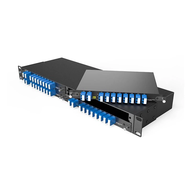
Dense Wavelength Division Multiplexing
The backbone of modern high-speed optical communication networks
Introduction to DWDM
Dense Wavelength Division Multiplexing (DWDM) is a revolutionary technology that has transformed the landscape of optical fiber communications. At its core, DWDM enables multiple optical signals to be transmitted simultaneously over a single optical fiber by using different wavelengths (colors) of laser light. This technology has been instrumental in meeting the ever-increasing demand for higher bandwidth in modern communication networks.
The concept behind DWDM is both elegant and powerful: instead of using a single wavelength to transmit data through a fiber optic cable, DWDM utilizes multiple wavelengths, each carrying its own independent data stream. This parallel transmission allows for an exponential increase in the capacity of existing fiber infrastructure, making DWDM an essential technology for telecommunications providers, data centers, and enterprise networks worldwide.
One of the key advantages of DWDM is its ability to dramatically increase bandwidth without requiring the installation of new fiber optic cables. This makes DWDM a cost-effective solution for network operators looking to expand their capacity. Additionally, DWDM systems are highly scalable, allowing network operators to add more wavelengths (and thus more capacity) as needed.
The evolution of DWDM technology has moved from a small number of fixed wavelengths to coherent systems that can carry dozens of channels across the C-band at 100G, 400G, or 800G per wavelength. The usable channel count is not a universal 80- or 160-channel limit: it depends on the frequency grid, occupied spectrum, filter passband, modulation format, and reach target. This progression is central to high-capacity telecom backbones and data center interconnect networks.
Key Benefits of DWDM
Capacity and Scalability
Massive Bandwidth
DWDM systems can carry terabits of data per second over a single fiber, dramatically increasing transmission capacity
Scalability
Additional wavelengths can be added to a DWDM system as needed, allowing for capacity expansion as traffic grows.
Cost and Compatibility
Cost Efficiency
DWDM maximizes existing fiber infrastructure, reducing the need for new cable installations and lowering overall costs.
Protocol Transparency
DWDM is transparent to data protocols, making it compatible with Ethernet, SONET/SDH, and other communication standards.
How DWDM Works
The DWDM Process
DWDM technology works by combining multiple optical signals onto a single fiber using different wavelengths of light. This process involves several key components working together seamlessly.
Electrical signals are converted to optical signals using lasers tuned to specific wavelengths
An optical multiplexer combines these different wavelengths onto a single fiber
The combined signal travels through the fiber optic cable
At the receiving end, a demultiplexer separates the signals by wavelength
Photodetectors convert the optical signals back to electrical signals

DWDM Technology Deep Dive
Wavelength Ranges
DWDM systems operate within specific wavelength ranges in the near-infrared spectrum, where optical fibers have minimal signal loss. The two primary wavelength bands used in DWDM are:
C-Band: 1530 nm to 1565 nm (most commonly used for long-haul DWDM)
L-Band: 1565 nm to 1625 nm (used for extended capacity in DWDM systems)
These bands offer optimal transmission characteristics, with very low attenuation (signal loss) in standard single-mode fiber.
Channel Spacing
A critical parameter in DWDM systems is channel spacing-the wavelength separation between adjacent channels. Common channel spacings in DWDM include:
100 GHz spacing (approximately 0.8 nm in the C-band)
50 GHz spacing (approximately 0.4 nm)
25 GHz spacing (approximately 0.2 nm) for high-density DWDM
12.5 GHz spacing for ultra-dense DWDM applications
Fixed grids such as 100, 50, 25, and 12.5 GHz remain useful references, but modern coherent DWDM networks may also use flexible-grid frequency slots defined by ITU-T G.694.1. The practical limit is set by occupied spectrum, filter passband, modulation format, and reach rather than by choosing the narrowest nominal spacing.
Key DWDM Components
Optical Transponders
Convert electrical signals to optical signals and vice versa, with precise wavelength control for DWDM compatibility.
Fixed and tunable options
Supports 10G, 40G, 100G, 400G, and 800G rates
Multiplexers/Demultiplexers
Combine (mux) multiple wavelengths onto a single fiber or separate (demux) them at the receiving end.
Thin-film filter technology
Arrayed Waveguide Gratings (AWG)
Optical Amplifiers
Boost optical signals without converting them to electrical signals, extending DWDM transmission distances.
Erbium-Doped Fiber Amplifiers(EDFA)
Raman amplifiers for extended reach
Optical Add-Drop Multiplexers
Allow specific wavelengths to be added or removed from a DWDM signal without disrupting other channels.
Reconfigurable (ROADM) options
Colorless, Directionless, Contentionless
Dispersion Management in Coherent DWDM
Legacy 10G direct-detect wavelengths may still require optical dispersion compensation, while 100G-and-higher coherent optics normally compensate chromatic dispersion in digital signal processing.
Do not specify a DCM by default for a new coherent route; its insertion loss consumes link margin
Check whether legacy wavelengths sharing the fiber still depend on optical compensation before removing existing DCMs; see compatible DWDM transponder cards
DWDM Monitoring Systems
Monitor performance parameters across all wavelengths in a DWDM system for optimal operation.
Power monitoring per channel
OSNR and BER measurements
DWDM System Architectures
DWDM systems can be deployed in various architectures to meet different network requirements:
Point-to-Point DWDM
The simplest DWDM architecture, connecting two locations directly. Ideal for high-capacity links between data centers or central offices.
Ring Architecture
DWDM nodes connected in a ring topology, providing redundancy and protection against fiber cuts. Traffic can be rerouted automatically if a failure occurs.
Mesh Architecture
A flexible DWDM architecture where nodes are interconnected with multiple paths, enabling dynamic routing and efficient bandwidth utilization.

Simplified IPoDWDM vs. Traditional DWDM
Simplified IPoDWDM is a good fit for metro and DCI routes where coherent pluggables can operate directly in router or switch ports and stay inside the required optical reach. Removing a separate transponder layer can reduce hardware, power, and operational touch points, but the host operating system, firmware, CMIS implementation, coherent optic, and optical line system must be qualified as one interoperable design.
Traditional transponder-based DWDM remains the safer choice when the route needs service aggregation, multi-span optical engineering, broader modulation choices, deeper optical-layer control, or fault isolation between IP equipment and the transport layer. For procurement, compare host/module compatibility, supported FEC and line modes, sparing requirements, and lifecycle policy instead of choosing an architecture only by chassis count.
For projects using coherent pluggables with an open line system, review the DWDM line system together with the router or switch compatibility matrix before a bulk order is approved.
How to Size a DWDM Link: Capacity, Reach and Engineering Margin
A modern DWDM system has no single maximum reach or capacity number. Reach is set by the selected coherent mode, FEC, transmitter power, receiver operating range, fiber attenuation, connector and splice loss, MUX/WSS insertion loss, amplifier noise, and the OSNR available at the receiver. Capacity is set by the usable spectrum, channel or slot width, modulation format, and per-wavelength line rate. A design that only multiplies "number of wavelengths × line rate" can therefore overstate both usable capacity and practical reach.
For a useful interoperability reference, OIF 400ZR defines 400G operation for amplified point-to-point DWDM links up to 120 km, while the unamplified single-wavelength application uses an 11 dB loss budget. Beyond that boundary, evaluate ZR+, a dedicated coherent transponder, or another line mode against the actual optical path instead of extrapolating the 400ZR distance figure. OIF has published 800ZR, while 1.6T coherent interoperability is the next standardization boundary rather than a universal current deployment baseline.
Four Checks Before You Approve the Link Budget
1. Spectrum and channel plan: Confirm the ITU-T G.694.1 frequency plan, occupied spectrum, and filter passband. A 25 GHz or 12.5 GHz nominal grid does not mean every coherent signal can operate in that width.
2. Passive optical loss: Include fiber attenuation, connectors, splices, MUX/DEMUX loss, ROADM/WSS loss, and an engineering margin. For an unamplified route, the total must remain within the exact transmitter/receiver specification.
3. Amplified coherent performance: Received power and OSNR/GOSNR, FEC threshold, and nonlinear penalties must all pass. A higher-power amplifier cannot recover OSNR that has already been consumed by accumulated ASE noise.
4. Installed-fiber evidence: Use OTDR traces, measured end-to-end loss, fiber type, and splice records instead of assuming a nominal distance. Standard G.652 single-mode fiber is common, while G.654-series fiber is used for long-distance transmission where its characteristics match the route design.
When the calculation shows limited margin, compare a coherent DCI transport platform, a different line mode, and the appropriate DWDM optical amplifier before adding hardware to the route.
DWDM Manufacturing Process
The production of DWDM components and systems requires precision engineering, advanced materials, and rigorous quality control to ensure optimal performance in demanding optical networks.
Component Design & Engineering
The manufacturing process begins with detailed design and engineering of each DWDM component using advanced CAD software. Engineers optimize for wavelength precision, minimal insertion loss, and thermal stability.
Precision Component Manufacturing
DWDM components like AWGs and thin-film filters are manufactured using photolithography and precision deposition techniques. These processes create structures with nanometer-scale accuracy critical for proper wavelength separation.
Optical Transceiver Production
Transceivers, the lasers, and detectors at the heart of DWDM systems, undergo specialized manufacturing. Laser diodes are precisely tuned to specific wavelengths, with temperature control mechanisms integrated for stability.
DWDM Frame Assembly
Components are integrated into DWDM frames with careful attention to thermal management and signal integrity. Backplanes and connectors are precision-mounted to minimize signal loss in the DWDM system.
Calibration & Testing
Each DWDM system undergoes extensive calibration to ensure precise wavelength alignment. Testing includes insertion loss measurement, crosstalk analysis, and performance verification across temperature ranges.
Quality Control in DWDM Manufacturing
Maintaining strict quality control is paramount in DWDM manufacturing due to the precision required for optimal performance. Our quality control process includes:
Environmental Testing
DWDM components are tested under extreme temperature and humidity conditions to ensure reliability in various deployment environments.
Optical Performance Verification
Each wavelength channel is verified for power levels, signal-to-noise ratio, and crosstalk to ensure DWDM system performance meets specifications.
Reliability Testing
Long-term burn-in tests and accelerated aging processes validate the reliability of DWDM components over their expected lifetime.
Compliance Verification
DWDM compliance should be mapped to the actual interface and deployment. ITU-T G.694.1 defines the DWDM frequency grid; G.698.2 and G.698.4 apply to relevant multivendor DWDM interface scenarios; and G.959.1 covers physical-layer interfaces for optical transport networks. Telcordia GR-253 should be specified only where SONET transport criteria are part of the project requirements.

DWDM Procurement and Commissioning: What to Verify Before Acceptance
A purchase specification should separate component compliance from end-to-end link acceptance. For a custom or OEM DWDM order, define the ITU channel plan, passband, maximum insertion loss, adjacent and non-adjacent channel isolation, connector type, operating-temperature range, and required test records before the PO is released. When a project moves from qualification samples to bulk production, also lock the approved BOM, firmware revision, and change-notification process; a sample that passes interoperability testing does not protect the project if a later production lot changes optics, filters, or firmware without requalification.
For active coherent equipment, record the host platform and software version together with the optical module. This is especially important in IPoDWDM: a pluggable can meet its optical specification but still fail operationally because of host firmware, CMIS implementation, telemetry, or management incompatibility. OIF CMIS and Coherent CMIS specifications make host/module management compatibility a practical line item in an OEM compliance matrix. For card-based projects, verify the exact DWDM card and supported host or chassis revision before repeat orders are released.
What Should Be Tested Before a DWDM Link Is Accepted?
1. Reconcile measured span loss with the design. Use bidirectional OTDR plus end-to-end loss testing and investigate unexplained connector, splice, or bend losses before configuring amplifier gain.
2. Measure each channel after the complete passive path. MUX/DEMUX and WSS insertion loss must be included; omitting these elements makes an unamplified reach calculation artificially optimistic.
3. Verify OSNR as well as received power on amplified routes. A receiver can sit inside its allowed dBm window while accumulated amplifier ASE leaves insufficient OSNR for the selected modulation and FEC. IEC 61280-2-9 defines an OSA-based method for DWDM OSNR measurement.
4. Archive pre-FEC BER, post-FEC performance, and coherent DSP telemetry under realistic channel loading. Do not copy a generic OSNR threshold into the acceptance specification; use the exact transponder/FEC mode threshold plus the project engineering margin.
For carrier and data-center projects, retain the measurements with the as-built channel plan, firmware record, and change history. Where amplification is part of the route, the acceptance package should also identify the installed optical amplifier model and operating settings.
Our DWDM Frame Solutions
We offer a comprehensive range of DWDM frames designed to meet diverse network requirements, from small-scale deployments to large, high-capacity networks. Each frame is engineered for scalability, reliability, and seamless integration into modern optical transport networks.

5U DWDM Frame
Our flagship DWDM solution, designed for large-scale deployments requiring maximum capacity and flexibility.
Supports up to 96 DWDM channels
Redundant power supplies
Integrated monitoring system
Hot-swappable components
19" rack-mountable design

2U DWDM Frame
A compact yet powerful DWDM solution ideal for medium-sized networks and edge deployments.
Supports up to 48 DWDM channels
Optional redundant power
Integrated wavelength monitoring
Hot-swappable transponders
Space-efficient 2U design

1U DWDM Frame
An ultra-compact DWDM solution perfect for small deployments and space-constrained environments.
Supports up to 16 DWDM channels
Low power consumption
Plug-and-play configuration
Integrated management interface
Ultra-compact 1U form factor
DWDM System Capabilities

DWDM System Features
Colorless Add-Drop
Supports any wavelength on any port
Directionless
Flexible routing in any direction
Contentionless
No wavelength conflicts
Spectrum Analysis
Real-time wavelength monitoring
High Speed
Supports 100G/400G/800G channels
Cloud Management
Remote monitoring and control
DWDM Applications

Long-Haul Telecommunications
DWDM is the foundation of long-haul fiber optic networks, enabling telecommunications providers to transmit massive amounts of data over thousands of kilometers. By amplifying optical signals without converting them to electrical form, DWDM systems minimize latency and maximize throughput across intercity and international links.
Modern undersea cables rely heavily on DWDM technology to carry internet traffic between continents, with each cable capable of transmitting terabits of data per second using hundreds of DWDM channels.

Data Center Interconnect (DCI)
As data centers grow in size and number, DWDM provides the high-bandwidth connections needed to link them together. DWDM-based DCI solutions enable seamless data replication, disaster recovery, and workload migration between facilities.
The low latency and high capacity of DWDM make it ideal for connecting geographically distributed data centers, supporting the demands of cloud computing and big data applications.

Metro Area Networks
In urban environments, DWDM enables service providers to deliver high-speed connectivity to businesses and residential areas. DWDM-based metro networks support multiple services on a single infrastructure, reducing costs while increasing capacity.

Enterprise Networks
Large enterprises with multiple campus locations use DWDM to connect their facilities with high-speed, secure links. DWDM allows enterprises to consolidate network services while future-proofing their infrastructure for increasing bandwidth demands.

5G Backhaul
The rollout of 5G networks is driving unprecedented demand for backhaul capacity. DWDM provides the high-bandwidth connections needed between 5G base stations and core networks, supporting the ultra-low latency and high throughput requirements of 5G services.
DWDM in the Digital Ecosystem
DWDM technology forms the backbone of our digital ecosystem, enabling the services and applications that define modern life. From streaming high-definition video to supporting real-time cloud computing, DWDM makes it all possible through its ability to carry massive amounts of data across long distances efficiently.
Video Streaming
Supports 4K/8K content delivery to millions simultaneously
Cloud Computing
Enables fast, reliable access to cloud resources worldwide
Mobile Networks
Backbone for 4G/5G networks supporting billions of devices
Financial Services
Supports high-frequency trading with ultra-low latency
The Future of DWDM Technology
Emerging Trends in DWDM
The 2026 DWDM roadmap is being shaped by coherent pluggables, IPoDWDM, flexible spectrum, open line systems, and higher per-wavelength rates. The practical shift is from maximizing a fixed channel count to matching spectral width, host compatibility, and optical reach to each service.
800ZR Now, 1.6T Next
OIF has published interoperable 800ZR specifications, while 1600ZR and 1600ZR+ work is defining the next 1.6 Tb/s coherent boundary. For procurement planning, standardized 800G interoperability and the transition toward 1.6T are more actionable than treating 3.2 Tb/s per wavelength as a current baseline.
Flexible Grid and Higher-Baud Coherent
ITU-T G.694.1 supports flexible DWDM frequency slots, so the design goal is no longer simply tighter fixed spacing. Higher-baud coherent signals may need wider spectral slots, and the selected slot width must preserve filter margin and reach.
IPoDWDM and Coherent Pluggables
Coherent optics are moving directly into routers and switches for suitable metro and DCI routes. This can remove a transponder layer, but it makes host firmware, CMIS support, optical telemetry, and line-system interoperability part of the deployment decision.
Open Line Systems and Disaggregation
Disaggregated optical systems separate coherent terminals from the line system and can improve vendor flexibility. The trade-off is greater responsibility for interoperability testing, operational ownership, and lifecycle coordination across multiple suppliers.
Current DWDM Market Direction
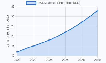
Current optical-transport demand is being pulled strongly by data center interconnect and disaggregated WDM deployments. Dell'Oro reported that the optical transport equipment market grew 10% in 2025, while direct WDM equipment purchases for DCI increased by nearly 40% and disaggregated WDM grew by about 40%. For 2026 planning, the more relevant signals are 800ZR/ZR+ adoption, IPoDWDM, and scale-across connectivity between AI data centers. See our high-capacity DCI solutions for related platform options.
Why Choose Our DWDM Solutions?
Configuration Transparency
Compare channel count, form factor, power redundancy, optical limits, and supported line rates against the project BOM before selecting a DWDM frame or line-system configuration.
Interoperability Checks
For coherent deployments, verify transponder, host firmware, FEC mode, CMIS support, and DWDM equipment compatibility before qualification samples move to a bulk order.
Acceptance Evidence
Request insertion-loss records, channel-power checks, relevant environmental or burn-in evidence, and firmware/change-control records so repeat orders can be verified against the approved configuration.