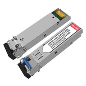
1.25G SFP BIDI 40km
1000BASE BIDI Single fiber bidirectional SFP series optical transceiver include 155Mb /s, 1.25Gb/s and other speed, the product supports a variety of transmission distance from 500m to 120km, the series of products use a single LC or SC optical interface, with low power consumption, small size, high reliability, wide temperature range and other characteristics. It is mainly used in Ethernet/SDH/SONET transmission environment.

- Product Introduction

Products Description
|
Compatible |
1.25G SFP BIDI |
Vendor Name |
FB-LINK |
|
Form Factor |
SFP |
Max Data Rate |
1.25G |
|
Wavelength |
1310/1550nm |
Max Cable Distance |
40km |
|
Connector |
Single LC |
Media |
SMF |
|
TX Power |
-2.0~3.0dBm |
Receiver Sensitivity |
<-24.0dBm |
|
Power Consumption |
≤1W |
Extinction Ratio |
>3.5dB |
|
DOM Support |
Yes |
Commercial Temperature Range |
0 to 70°C (32 to 158°F) |
|
Protocols |
Fast Ethernet, Gigabit Fibre Channel, MSA Compliant |
Warranty |
3 Years |
Product Reliability

Application
applicationapplicationapplicationapplication
Shipping

Packages

When network infrastructure demands efficient, cost-effective solutions for extending fiber connections, optical transceivers have become the cornerstone of modern telecommunications. Among the various options available, bidirectional small form-factor pluggable modules represent a significant advancement in how we approach fiber optic networking.
What Makes Bidirectional Technology Revolutionary
Traditional fiber optic connections require two separate fiber strands-one for transmission and one for reception. Bidirectional technology changes this paradigm entirely by enabling data transmission in both directions over a single fiber strand. This innovation reduces infrastructure costs by half while maintaining the same level of performance and reliability that network administrators expect.
The technology achieves this through wavelength division multiplexing, where different wavelengths travel simultaneously on the same fiber without interference. One end transmits at one wavelength while receiving at another, and the opposite end does the reverse. This elegant solution has made optical transceivers increasingly popular in metropolitan area networks, campus backbones, and enterprise deployments.
Technical Specifications That Matter
High-quality optical transceivers must meet rigorous performance standards to ensure reliable operation. The gigabit data rate capability ensures compatibility with modern network equipment while providing sufficient bandwidth for demanding applications. When evaluating these modules, several critical specifications determine their suitability for specific deployments.
Power output levels typically range from negative two to positive three decibels referenced to one milliwatt, providing adequate signal strength for extended distances. Receiver sensitivity specifications indicate the minimum signal level required for proper operation, with values around negative twenty-four decibels ensuring reliable reception even after signal degradation over long fiber runs.
Single-mode fiber compatibility extends the usable distance far beyond what multimode solutions can achieve. The tight laser beam pattern and minimal modal dispersion enable connections spanning dozens of kilometers without requiring signal regeneration or amplification.
Distance Capabilities and Real-World Applications
The ability to bridge significant distances makes these optical transceivers ideal for various scenarios. Enterprise campuses with buildings separated by several kilometers benefit from direct fiber connections without intermediate equipment. Service providers use these modules to connect central offices with remote terminals, reducing the need for expensive regeneration sites.
Metropolitan area networks leverage this technology to interconnect data centers, corporate offices, and colocation facilities. The extended reach eliminates the need for multiple switching points, reducing latency and potential failure points while simplifying network architecture.
Digital Diagnostics and Network Management
Modern optical transceivers incorporate digital optical monitoring capabilities that provide real-time visibility into module performance. Network administrators can monitor transmit power, receive power, temperature, supply voltage, and laser bias current without specialized test equipment.
This diagnostic information enables proactive maintenance strategies. Instead of waiting for complete failures, network teams can identify degrading modules and schedule replacements during maintenance windows. The ability to remotely monitor optical power levels helps quickly isolate fiber breaks, dirty connectors, or other issues affecting link quality.
Temperature Considerations for Deployment Environments
Commercial temperature ratings suit the majority of indoor installations where climate control maintains stable conditions. Data centers, telecommunications rooms, and office environments typically remain well within these specifications year-round.
However, deployments in semi-outdoor enclosures, unheated buildings, or locations with variable climate conditions require careful consideration. While commercial-rated optical transceivers operate reliably across a standard range, extreme temperatures can affect laser performance and module lifespan.
Protocol Compatibility and Standards Compliance
Industry standards ensure interoperability between equipment from different manufacturers. Multi-source agreement compliance guarantees that these optical transceivers work seamlessly with switches, routers, and media converters following the same specifications.
Support for both Fast Ethernet and Gigabit protocols provides flexibility during network upgrades. Organizations can deploy the same module type across different network segments, simplifying inventory management and reducing the variety of spare parts required.
Power Efficiency in Modern Networks
With growing emphasis on reducing data center energy consumption, power-efficient optical transceivers contribute to overall sustainability goals. Lower power consumption reduces heat generation, decreasing cooling requirements and associated energy costs.
The electrical power draw of approximately one watt per module may seem minimal, but it accumulates significantly in large deployments. A fully populated switch with dozens of ports can see substantial power savings by choosing efficient modules.
Installation Best Practices
Proper installation ensures optimal performance and longevity of optical transceivers. Always inspect fiber connectors before insertion, using approved cleaning methods to remove dust and contaminants. Never look directly into fiber ends, as invisible infrared laser light can cause eye damage.
Verify that fiber patch cables match the required connector type and polish specification. Physical contact polishes provide the lowest insertion loss and best return loss characteristics for single-mode applications.
Handle modules carefully by the body rather than the bail clasp, which serves only for extraction. Electrostatic discharge can damage sensitive electronics, so use proper grounding techniques when handling optical transceivers outside of their protective packaging.
Troubleshooting Common Issues
When links fail to establish, systematic troubleshooting quickly identifies the root cause. First, verify that both ends use compatible wavelength pairs-mismatched transceivers won't communicate. Check that fiber polarity is correct; bidirectional connections require specific orientation.
Use digital diagnostics to verify transmit and receive power levels fall within acceptable ranges. Excessive insertion loss suggests dirty connectors, damaged fiber, or improper splicing. If receive power is too high, optical attenuators may be necessary to prevent receiver saturation.
Frequently Asked Questions
What is the maximum distance these optical transceivers can reliably transmit data?
These modules support connections up to forty kilometers over single-mode fiber under optimal conditions. Actual achievable distance depends on fiber quality, number of splices and connectors, and accumulated insertion loss along the path. For mission-critical links near the maximum distance specification, conducting an optical power budget calculation ensures adequate margin.
Can I mix different brands of bidirectional transceivers on the same link?
Yes, as long as both optical transceivers follow the same wavelength pairing and industry standards. One end must transmit at the same wavelength the other end receives, and vice versa. Most manufacturers clearly mark wavelength specifications on the module label. Testing compatibility before deployment in production environments is always recommended.
How do I know if my switch supports digital optical monitoring?
Check your switch documentation for DOM, DDM, or digital diagnostics support. Most modern managed switches include this capability, accessible through command-line interfaces or web management interfaces. Even if your switch doesn't display diagnostic data, the optical transceivers still provide the information-you simply need compatible equipment to read it.
What causes optical transceivers to fail prematurely?
The most common failure causes include excessive heat, power supply fluctuations, electrostatic discharge during handling, and contaminated fiber connectors causing back-reflection. Operating modules beyond their specified temperature range significantly reduces lifespan. Ensuring proper ventilation, clean power, and careful handling prevents the majority of premature failures.
Do these modules work with existing fiber infrastructure?
Standard single-mode fiber installed over the past several decades works perfectly with these optical transceivers. The common core diameter and numerical aperture specifications ensure compatibility. However, verify that your fiber plant meets cleanliness standards and that connector types match. Older connectors may require adapter cables or re-termination.
How often should I clean fiber connectors?
Clean connectors before every mating when possible, especially for critical links. Even in clean data center environments, airborne particles settle on exposed fiber ends. A proper cleaning regimen using approved solvents and lint-free materials takes only seconds per connector but prevents countless hours of troubleshooting mysterious link issues.
What warranty coverage should I expect?
Quality optical transceivers typically include three-year warranties covering manufacturing defects. This protection demonstrates manufacturer confidence in their products and provides peace of mind for infrastructure investments. Always retain purchase documentation and understand the warranty claim process before deployment.
Can these modules operate in outdoor environments?
Standard commercial-temperature optical transceivers suit indoor installations with climate control. For outdoor enclosures, hardened cabinets with temperature regulation can maintain suitable operating conditions. Alternatively, industrial-temperature-rated modules specifically designed for harsh environments provide extended temperature ranges and enhanced durability.
Conclusion: Making Informed Decisions
Selecting appropriate optical transceivers requires balancing technical specifications, application requirements, and budget constraints. Bidirectional technology offers compelling advantages for single-fiber deployments while maintaining the performance and reliability demanded by modern networks.
Understanding key specifications-data rates, wavelengths, distance capabilities, and diagnostic features-enables informed decision-making. Proper installation practices and ongoing monitoring through digital diagnostics ensure these critical infrastructure components deliver years of reliable service.
Whether upgrading existing networks or designing new installations, optical transceivers continue evolving to meet increasing bandwidth demands while reducing costs and complexity. Investing in quality modules from reputable manufacturers provides the foundation for robust, future-proof network infrastructure.
Hot Tags: