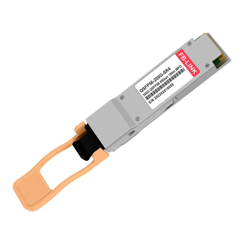


200GBASE-SR4 QSFP56 Optical Transceiver
A 4-channel parallel multimode fiber optic module built on 850nm uncooled VCSEL technology and 50G PAM4 signaling. Designed for high-density, low-power 200 Gigabit Ethernet connectivity up to 100 meters over OM4 fiber — the go-to short-reach solution for modern spine-leaf data center architectures.

- Product Introduction
Complete Technical Specifications
All values are measured under standard commercial operating conditions (0 °C to 70 °C) with a single 3.3 V supply.
| Parameter | Specification | Parameter | Specification |
|---|---|---|---|
| Product Name | 200GBASE-SR4 QSFP56 Optical Transceiver | Vendor | FB-LINK |
| Form Factor | QSFP56 | Max Data Rate | 212.5 Gbps (4×53.125 Gbps) |
| Modulation | PAM4 (50G per lane) | Wavelength | 850 nm (nominal) |
| Laser Type | Uncooled 4-ch VCSEL Array | Photodetector | 4-ch PIN Photodiode Array |
| Connector | MTP/MPO-12 UPC | Fiber Type | OM3 / OM4 / OM5 MMF |
| Max Distance (OM3) | 70 m | Max Distance (OM4/OM5) | 100 m |
| TX Output Power | −3 to +3 dBm | Receiver Sensitivity | < −6.5 dBm |
| Power Budget | 3.5 dB | Receiver Overload | +5 dBm |
| Power Consumption | ≤ 5 W | Extinction Ratio | ≥ 3 dB |
| CDR | TX & RX Built-in | FEC | RS-FEC (544,514) |
| Electrical Interface | 200GAUI-4 | DDM / DOM | Yes - per-lane monitoring |
| Management Interface | CMIS v4.0 | Hot-Pluggable | Yes |
| Operating Temp. | 0 °C to +70 °C (Commercial) | Supply Voltage | 3.3 V single rail |
| Standards | IEEE 802.3cd / 802.3bs, QSFP56 MSA | Compliance | CE, FCC, RoHS |
| Dual-Rate Support | 200G (PAM4) / 100G (NRZ) | Warranty | 3 Years |
What Makes This 850nm Parallel-Optics Module Different
Among the 200G transceiver family, the SR4 variant occupies a unique niche: it is the only option that pairs uncooled VCSEL lasers with multimode fiber for the shortest, most cost-effective links. Here is what sets it apart from the FR4, DR4, and LR4 alternatives - and from lower-speed modules it replaces
Uncooled 850nm VCSEL Array
Where FR4 and LR4 modules depend on temperature-controlled DFB lasers, this short-reach multimode transceiver uses four uncooled vertical-cavity surface-emitting lasers. That means zero TEC power draw, simpler thermal management, and total dissipation under 5 watts - roughly 40% less than comparable single-mode alternatives at the same data rate.
100G / 200G Dual-Rate Operation
This module supports both 212.5 Gb/s (PAM4) and 103.1 Gb/s (NRZ) aggregate signaling. Few competing products offer genuine dual-rate operation, making it a uniquely flexible investment for phased network migration - run it at 100G today on legacy fabric, then switch to full 200 Gigabit speed when spine switches are upgraded.
Integrated CDR - No External Retimer
Clock and Data Recovery circuits are built into both transmit and receive paths. This on-module signal conditioning removes the need for external retimer chips on the host board - a cost and power saving that compounds quickly when deploying hundreds of ports across an enterprise network fabric.
MPO-12 - Direct Cable Reuse from 100G
Organizations already running 100GBASE-SR4 on MPO-12 multimode trunk cables can upgrade to this 200G parallel optics module without re-cabling. The identical connector footprint means the switch-port swap is the only hardware change - a migration advantage no single-mode variant can match.
CMIS 4.0 Digital Diagnostics (DDM/DOM)
Per-lane optical power, laser bias, temperature, and supply voltage are exposed through the Common Management Interface Specification. The telemetry integrates natively with SNMP and gNMI stacks, enabling predictive maintenance in environments where thousands of ports must be supervised in real time.
RS-FEC at the Physical Layer
Reed-Solomon Forward Error Correction is essential for PAM4 links where the narrower eye opening raises raw BER. This module supports RS-FEC (544,514), correcting burst errors so that the post-FEC bit-error rate meets IEEE 802.3cd requirements - guaranteeing lossless transport over the full 100-meter reach on OM4 fiber.
Where This Short-Reach Multimode Module Excels
Purpose-built for high-density parallel fiber links under 100 meters, this module's specific combination of 850nm VCSEL technology, low power envelope, and MPO-12 connectivity makes it the dominant choice across several core deployment scenarios.
Spine-Leaf Data Center Fabrics
Typical Distance: 10 – 100 m
In leaf-spine topologies, every top-of-rack switch uplinks to multiple spine switches through short multimode runs. Deploying this 200 Gigabit Ethernet transceiver on those uplinks doubles the bandwidth of existing 100G links without replacing a single MPO-12 trunk cable. A standard 32-port spine switch fully populated with these modules delivers 6.4 Tbps in a single rack unit at roughly 160 W of optics power - leaving valuable thermal headroom for the switch ASIC itself.
6.4T
0
<5W
GPU Cluster & High-Performance Computing
Latency-Critical • High Port Count
AI training workloads on GPU clusters demand massive all-to-all bandwidth with minimal latency. This 850nm multimode optical module plugs directly into high-performance compute adapters, forming the physical layer for RDMA and MPI traffic between hundreds of nodes. The integrated CDR and on-chip RS-FEC ensure clean signal integrity even in densely packed racks where electromagnetic noise is substantial - keeping the fabric lossless without external amplification.
PAM4
RDMA
<5W
Breakout Connectivity: 200G-to-4×50G Server Fan-Out
A single 200 Gigabit port on the aggregation switch can break out into four individual 50G SFP56 connections at the server side via an MPO-to-4×LC harness cable. This approach consolidates four server-facing ports into one switch port, dramatically improving port utilization and reducing per-server cost. The same module also supports a 2×100G breakout configuration for dual-homed 100G server NICs.
This flexibility is especially valuable during rolling upgrades: existing 100G NICs connect via breakout today, while newly provisioned 200G NICs attach natively - all through the same aggregation port.

Other Deployment Environments
Beyond spine-leaf and HPC, this low-power 200G multimode transceiver is regularly deployed in enterprise campus aggregation layers where buildings sit within 100 meters, private cloud environments connecting storage arrays to compute via multimode structured cabling, and broadcast production facilities transferring uncompressed high-resolution video between edit bays over parallel fiber links.
Choosing the Right 200G Variant
The table below highlights why the SR4 multimode variant is the optimal pick for reaches under 100 meters - and when an alternative makes more sense.
| Attribute | SR4 (This Product) | FR4 | DR4 | LR4 |
|---|---|---|---|---|
| Fiber Type | OM3/OM4/OM5 MMF | SMF | SMF | SMF |
| Wavelength | 850 nm (VCSEL) | CWDM 1310 nm | 1310 nm | CWDM 1310 nm |
| Connector | MPO-12 | LC Duplex | MPO-12 | LC Duplex |
| Max Reach | 100 m | 2 km | 500 m | 10 km |
| Typical Power | ≤ 5 W | ~7 W | ~6 W | ~8.5 W |
| Module Cost | Lowest | Medium | Medium | Highest |
| Fiber Cost | Low (MMF) | Medium (SMF) | Medium (SMF) | Medium (SMF) |
| Breakout | 4×50G / 2×100G | - | - | - |
| Best Fit | Intra-DC spine-leaf & server | Campus / Building link | Data Center Interconnect | Metro & Long DCI |
For intra-data-center links within 100 m, the SR4 variant delivers the lowest total cost of ownership by combining an inexpensive VCSEL laser source with multimode fiber that is cheaper to terminate and splice than single-mode. When reach requirements exceed 100 m, explore the FB-LINK FR4 or DR4 modules.
Migrating from 100G to 200G: A Practical Guide
One of the strongest benefits of this 200 Gigabit multimode transceiver module is the seamless upgrade path it offers from existing 100GBASE-SR4 deployments.
What You Keep
Your entire multimode fiber plant - OM3 or OM4 trunks, MPO-12 patch panels, cassettes, and harness cables - remains untouched. The physical-layer connector interface is identical to the 100G QSFP28 SR4 it replaces. This is a substantial cost advantage: re-cabling a data center hall can cost more than the switch and optics upgrade combined.
What Changes
The switch platform must expose QSFP56-capable ports (or QSFP-DD ports running in backward-compatible mode). Most current-generation data center switches already support this natively or through firmware activation. Once enabled, inserting the new module is plug-and-play - the host reads the CMIS 4.0 advertisement and auto-configures the lane rate.
Phased Rollout Strategy
Because this module supports dual-rate operation, you can deploy it on uplinks first - doubling backbone bandwidth - while leaf-to-server links remain at 100G. As server NICs are refreshed, the same aggregation ports seamlessly accept native 200 Gigabit connections. This phased approach spreads capital expenditure across budget cycles without requiring any forklift upgrades.
Multi-Vendor Switch Compatibility
FB-LINK transceivers are MSA-compliant and validated for interoperability with major networking platforms. Our in-house compatibility lab programs EEPROM coding for each target platform, ensuring reliable plug-and-play operation.
This standards-based 200 Gigabit Ethernet optical module has been tested with equipment from Cisco, Arista, Juniper, Huawei, Mellanox, and other widely deployed networking platforms. If your specific switch model requires custom coding, our engineering team can prepare a tailored EEPROM profile - contact us with your hardware details for compatibility confirmation.
Quality Assurance & Certifications
Every unit shipped passes a multi-stage inspection regime that goes beyond minimum compliance.
Component-Level Traceability
Optical chips - including the 850nm VCSEL die and PIN photodetector arrays - are sourced exclusively from tier-one fabrication partners such as Broadcom, Semtech, and other qualified suppliers listed in our vendor qualification program. Each component lot is incoming-inspected and linked to the final module serial number, enabling full traceability from silicon to shipment.
End-of-Line Functional Testing
100 % of finished modules undergo automated optical-power, sensitivity, and eye-diagram testing across all four lanes at both room temperature and the 70 °C upper boundary. Units that pass functional testing then enter an extended burn-in cycle at elevated temperature and voltage to screen infant-life failures before shipment.
Certifications
This product holds CE (EU), FCC Part 15 Class A (US), and RoHS compliance certification. FB-LINK's manufacturing facility operates under ISO 9001:2015 quality management and ISO 14001:2015 environmental management systems.
Frequently Asked Questions
Q: Can this module fall back to 100G on platforms that only support QSFP28 speeds?
A: The module supports 103.1 Gb/s aggregate operation in addition to its native 212.5 Gb/s rate, but the host port must be a QSFP56-capable slot (or a QSFP-DD slot in backward-compatible mode). It cannot be inserted into a QSFP28-only port - the electrical pin assignment differs. For 100G operation on a QSFP56 port, the switch firmware negotiates the lower rate automatically.
Q: Which multimode fiber grade delivers the best performance?
A: OM4 (or OM5) fiber is recommended for the full 100-meter reach. OM3 is supported but limits maximum distance to 70 m. If your facility is installing new structured cabling, OM4 offers the best balance of cost and headroom. OM5 wideband multimode provides marginal distance improvement today but reserves capacity for future SWDM wavelength-division schemes.
Q: How does the 4×50G breakout work in practice?
A: You need a compatible MPO-12 to 4×LC duplex breakout harness cable. Each of the four electrical lanes maps to a separate fiber pair, terminating at an SFP56 50G SR module on the server NIC. The switch must support breakout configuration at the CLI or controller level. A 2×100G breakout requires an MPO-12 to 2×MPO-8 harness and corresponding 100G SR2 modules on the far end.
Q: Is RS-FEC always required when running at 200 Gigabit speed?
A: For PAM4 operation, RS-FEC is effectively mandatory per IEEE 802.3cd. The reduced eye height raises the raw bit-error rate to approximately 2.4×10⁻⁴, which is only acceptable once FEC corrects it down to the 10⁻¹⁵ floor. Most switch platforms enable RS-FEC automatically when a 200G link comes up, so no manual intervention is typically needed.
Q: What is the minimum order quantity and lead time?
A: FB-LINK offers volume pricing at 10+, 50+, 100+, and 500+ tiers, with sample evaluation kits available for qualifying projects. Standard lead time is 2–5 business days for stocked configurations; custom-coded variants (specific vendor EEPROM) typically ship within 5–7 business days. Contact our sales team for a custom quotation.
Q: How does the power consumption compare to running two separate 100G SR4 modules?
A: A single module at under 5 W is more power-efficient than two 100G QSFP28 units delivering the same aggregate bandwidth (typically 3.5 W each, or 7 W combined). It also occupies only one switch port instead of two, further reducing system-level power draw from the switch ASIC. At scale, this translates to measurably lower electricity and cooling costs.
Hot Tags: 200GBASE-SR4 QSFP56 optical transceiver, 200G QSFP56 SR4, 200G multimode transceiver module, QSFP56 850nm VCSEL module, 200G SR4 PAM4 transceiver
You Might Also Like