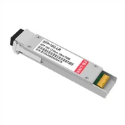
10GBASE XFP ER
The 10GBASE XFP ER compatible XFP transceiver supports up to 40km over a standard pair of single mode fiber (SMF).

- Product Introduction
Item Spotlights
● Max. Power Consumption 3W
● Tested in Targeted Switch for Superior Performance, Quality and Reliability
● Hot Pluggable XFP MSA Compliant
● Cooled 1550nm EML and PIN receiver
● Digital Optical Monitoring Capability for Strong Diagnostic Capabilities
● Optical Interoperability with 10GBASE XENPAK, X2, and XFP Interfaces on the Same Link
● Class 1 Laser Safety and RoHS Compliant
● IEEE 802.3ae Compliant
● RoHS-6 Compliant (lead-free)
● Supports 9.95Gb/s to 11.3Gb/s bit rates
Description
|
Compatible |
10GBASE XFP ER |
Vendor Name |
FB-LINK |
|
Form Factor |
XFP |
Max Data Rate |
10.3125Gbps |
|
Wavelength |
1550nm |
Max Cable Distance |
40km |
|
Connector |
Duplex LC |
Media |
SMF |
|
Transmitter Type |
EML |
Receiver Type |
PIN |
|
TX Power |
0~4dBm |
Receiver Sensitivity |
<-16dBm |
|
Power Consumption |
≤2W |
Extinction Ratio |
>8.2dB |
|
DDM/DOM |
Yes |
Commercial Temperature Range |
0 to 70°C (32 to 158°F) |
|
Protocols |
SFP+ MSA Compliant, CPRI, eCPRI |
Warranty |
3 Years |
When network infrastructure demands reliable, high-speed connectivity over extended distances, choosing the right optical transceivers becomes critical. The XFP form factor has established itself as a trusted solution for 10 Gigabit Ethernet applications, particularly in scenarios requiring transmission distances up to 40 kilometers. Understanding the capabilities and applications of these modules helps organizations make informed decisions about their network expansion and upgrade strategies.
Understanding XFP Technology in Modern Networks
Extended reach 10 Gigabit optical transceivers represent a significant advancement in fiber optic communication technology. These modules utilize sophisticated laser technology and advanced receiver designs to maintain signal integrity across substantial distances. The 1550nm wavelength operates in a low-attenuation window of single mode fiber, making it ideal for metropolitan area networks and long-haul applications.
The engineering behind these optical transceivers incorporates electronically modulated laser (EML) technology, which provides superior performance compared to directly modulated lasers. This technology enables consistent signal quality even at maximum transmission distances, ensuring reliable data delivery for mission-critical applications.
Key Applications and Use Cases
Telecommunications providers rely heavily on these optical transceivers for backbone infrastructure. The 40-kilometer reach makes them perfect for connecting central offices, cell towers, and metropolitan aggregation points without requiring signal regeneration. This capability significantly reduces infrastructure costs while maintaining high performance standards.
Data centers increasingly deploy these modules for disaster recovery and backup connectivity between geographically separated facilities. The extended reach allows organizations to establish secure, high-bandwidth connections between primary and secondary data centers, ensuring business continuity and data redundancy.
Enterprise networks benefit from these optical transceivers when connecting campus buildings across cities or linking regional offices. The combination of 10 Gigabit bandwidth and long-distance capability provides ample capacity for video conferencing, cloud applications, and data synchronization.
Technical Advantages and Performance Benefits
Modern optical transceivers incorporate digital diagnostic monitoring capabilities, providing network administrators with real-time visibility into module performance. This feature enables proactive maintenance by monitoring parameters such as temperature, voltage, laser bias current, transmit power, and receive power. Early detection of degradation patterns helps prevent network outages and optimize replacement schedules.
The hot-pluggable design of these modules allows for seamless installation and replacement without powering down network equipment. This capability minimizes network disruption during maintenance windows and enables rapid response to hardware failures.
Interoperability represents another crucial advantage. These optical transceivers work seamlessly with various 10 Gigabit interface types, including XENPAK and X2 modules, providing flexibility in network design and equipment selection. This compatibility ensures smooth integration into existing infrastructure regardless of vendor or form factor.
Energy Efficiency and Environmental Considerations
Power consumption remains a critical consideration in modern data centers and telecommunications facilities. Advanced optical transceivers achieve impressive performance while maintaining low power consumption profiles, typically operating at 2 watts or less. This efficiency reduces operational costs and minimizes heat generation within equipment chassis.
Environmental compliance has become increasingly important in technology procurement. Modern modules meet RoHS-6 standards, eliminating hazardous substances like lead from manufacturing processes. This compliance ensures responsible disposal and reduces environmental impact throughout the product lifecycle.
Installation and Deployment Best Practices
Proper installation of optical transceivers begins with fiber optic cable preparation. Single mode fiber must be clean and properly terminated with duplex LC connectors. Even microscopic contamination can significantly degrade performance or cause complete link failure. Using proper cleaning tools and techniques ensures optimal optical power transfer.
When deploying these modules, consider the entire link budget including connector losses, splice losses, and fiber attenuation. While the modules support 40-kilometer transmission, actual achievable distance depends on fiber quality and total system loss. Professional installation and testing verify that all parameters fall within acceptable ranges.
Network equipment compatibility should be verified before deployment. While these optical transceivers follow industry standards, testing with specific switch and router models ensures full functionality including diagnostic monitoring features. Many manufacturers provide compatibility matrices to guide selection.
Troubleshooting and Maintenance
Diagnostic monitoring capabilities built into modern optical transceivers simplify troubleshooting processes. When link issues occur, administrators can immediately check transmit and receive power levels, comparing them against specified thresholds. Deviations from normal operating ranges quickly identify whether problems originate from the transmitter, receiver, or fiber plant.
Temperature monitoring helps identify environmental issues that might affect module performance. Excessive temperatures can indicate inadequate chassis cooling or high ambient conditions requiring attention. Maintaining proper operating temperatures extends module lifespan and ensures consistent performance.
Regular monitoring of these optical transceivers identifies gradual degradation before it impacts network performance. Laser output power naturally decreases over time, and receiver sensitivity may drift. Establishing baseline measurements and tracking trends enables predictive maintenance strategies.
Future-Proofing Network Infrastructure
While 10 Gigabit technology continues serving many applications effectively, organizations should consider future bandwidth requirements when designing networks. These optical transceivers provide substantial headroom for most current applications, but rapidly growing data volumes may eventually require higher-speed solutions.
The modular nature of these optical transceivers facilitates future upgrades. When bandwidth requirements exceed 10 Gigabit capacity, organizations can simply replace modules with higher-speed versions, often without changing fiber infrastructure. This upgradeability protects investment in fiber plant and reduces total cost of ownership.
Standards compliance ensures long-term viability. Modules adhering to IEEE 802.3ae and XFP MSA standards maintain compatibility with current and future equipment generations. This standards-based approach prevents vendor lock-in and ensures competitive pricing through market availability.
Frequently Asked Questions
What is the difference between 10GBASE-ER and other 10 Gigabit standards?
The "ER" designation stands for Extended Reach, indicating support for distances up to 40 kilometers over single mode fiber. Other standards like 10GBASE-SR support shorter distances (typically up to 300 meters) over multimode fiber, while 10GBASE-LR reaches 10 kilometers. The wavelength also differs, with ER using 1550nm compared to 1310nm for LR and 850nm for SR variants.
Can these modules work with fiber that exceeds 40 kilometers?
While the specified maximum distance is 40 kilometers, actual achievable distance depends on total link loss. High-quality fiber with minimal splices and clean connections might support slightly longer distances, but operation beyond specifications cannot be guaranteed. For distances exceeding 40 kilometers, consider optical amplifiers or higher-power modules specifically rated for extended distances.
How do I know if my switch supports these optical transceivers?
Check your switch documentation for XFP port availability and 10GBASE-ER support. Most switches with XFP slots support multiple 10 Gigabit standards. Verify that the switch firmware is current, as older versions might have compatibility limitations. Many switches automatically detect and configure optical transceivers upon installation.
What maintenance do these modules require?
Regular inspection and cleaning of optical connectors represents the primary maintenance requirement. Before connecting or disconnecting modules, inspect fiber end faces for contamination and clean using appropriate tools. Monitor diagnostic parameters periodically to detect degradation trends. Keep modules in protective packaging when not installed to prevent contamination and physical damage.
Why is my link showing high error rates despite good optical power levels?
High error rates with acceptable power levels often indicate chromatic dispersion or polarization mode dispersion in the fiber plant. These effects become more pronounced at longer distances and higher data rates. Verify that you're using standard single mode fiber appropriate for 1550nm operation. Additionally, check for fiber bends exceeding minimum bend radius specifications, which can cause signal distortion.
Are these optical transceivers compatible with modules from other manufacturers?
Yes, standards-compliant modules from different manufacturers typically interoperate successfully. Both ends of the link don't need to use identical modules as long as they support the same standard (10GBASE-ER) and wavelength. However, diagnostic monitoring protocols might vary slightly between vendors, potentially affecting management system visibility.
What's the expected lifespan of these modules?
Quality optical transceivers typically provide 10-15 years of reliable operation under normal conditions. Actual lifespan depends on operating environment, thermal management, and duty cycle. Regular monitoring of diagnostic parameters helps identify aging modules before failure occurs. Most manufacturers provide multi-year warranties reflecting confidence in module longevity.
Can I use these modules for SONET/SDH applications?
Yes, these optical transceivers support both Ethernet and SONET/SDH protocols. The modules operate at bit rates compatible with OC-192/STM-64 SONET/SDH standards while also supporting 10 Gigabit Ethernet. This versatility makes them suitable for telecommunications networks that transport multiple protocol types over common infrastructure.
Hot Tags:
You Might Also Like