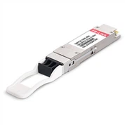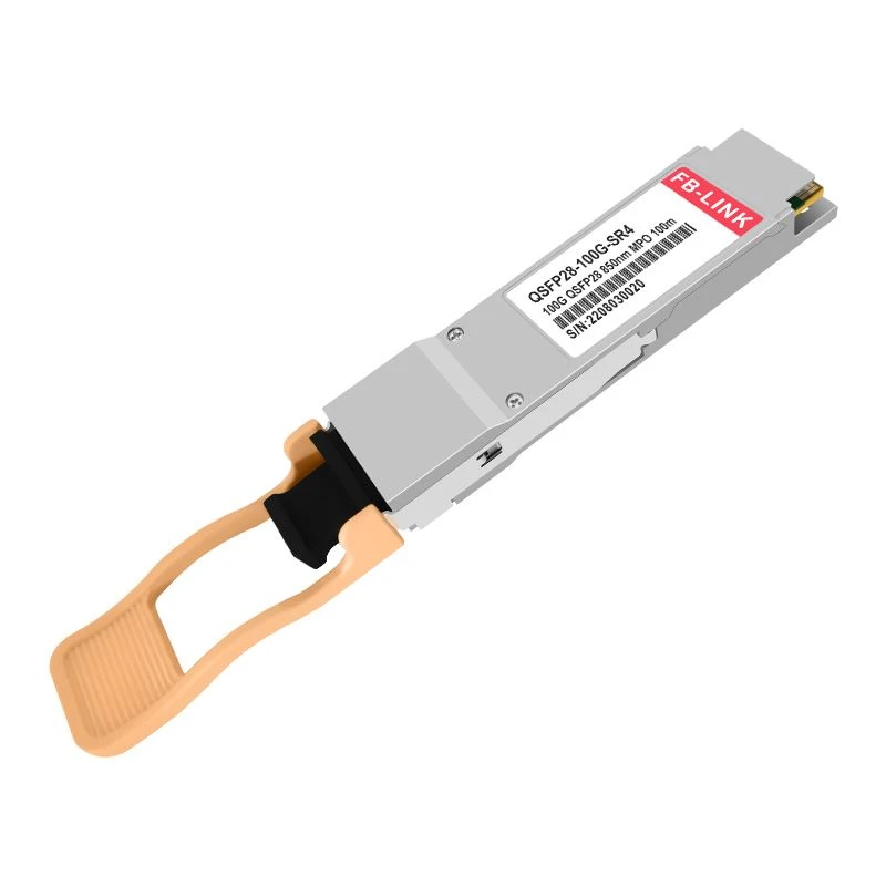
100GBASE SR4
The 100GBASE QSFP28 SR4 is a Four-Channel, Pluggable, Parallel, Fiber-Optic QSFP28Transceiver for IEEE 802.3bm,100GBASE SR4 Applications,or 100G Gigabit Ethernet and Infiniband and FDR/EDR Applications.

- Product Introduction
Item Spotlights
● Built-in Macom Chip, and Max. Power Consumption 2.5W
● Tested in Targeted Switches for Superior Performance, Quality, and Reliability
● High-Speed Electrical Interface Compliant to IEEE 802.3bm
● Support 100G to 4x25G Breakout Application
● Hot Pluggable QSFP28 MSA Compliant
● Class 1 FDA Laser Safety and RoHS Compliant
● Digital Optical Monitoring Capability for Strong Diagnostic Capabilities
Specifications
| Compatible | 100GBASE SR4 | Vendor Name | FB-LINK |
| Form Factor | QSFP28 | Max Data Rate | 103.125Gbps |
| Wavelength | 850nm | Max Cable Distance | 70m@OM3/100m@OM4 |
| Connector | MTP/MPO-12 | Media | MMF |
| Transmitter Type | VCSEL 850nm | Receiver Type | PIN |
| TX Power | -8.4~2.4dBm | Receiver Sensitivity | <-10.3dBm |
| Powerbudget | 1.9dB | Receiver Overload | 2.4dBm |
| Power Consumption | ≤1.8W | Extinction Ratio | >3dB |
| DDM/DOM | Supported | Commercial Temperature Range | 0 to 70°C (32 to 158°F) |
| CDR (Clock and Data Recovery) | TX & RX Built-in CDR | FEC Function | Supported |
| Protocols | IEEE 802.3bm, QSFP28 MSA, SFF-8665, SFF-8636, RoHS, CPRI, eCPRI | Warranty | 3 Years |
Our Factory

workshop

workshop

workshop

workshop
Related products

25G SFP28 SR

200G QSFP56 to 2*100G QSFP28

MPO-MPO Patch Cord

EDFA Optical Amplifier
High-speed data transmission has become the backbone of modern network infrastructure. As enterprises and data centers demand faster connectivity, optical transceivers have evolved to meet these escalating requirements. Among the most powerful solutions available today is the 100GBASE SR4 QSFP28 module, a technology that's revolutionizing how organizations handle massive data flows.
Understanding Modern Optical Transceivers Technology
Optical transceivers serve as the critical bridge between electronic and optical signals in network systems. These compact devices convert electrical signals into optical signals for transmission over fiber optic cables, then reverse the process at the receiving end. The technology has advanced dramatically, with contemporary optical transceivers supporting speeds that were unimaginable just a decade ago.
The QSFP28 form factor represents a significant leap forward in transceiver design. By utilizing four parallel channels operating simultaneously, these optical transceivers achieve aggregate speeds exceeding 100 gigabits per second. Each channel handles approximately 25 Gbps, working in concert to deliver enterprise-grade performance in a hot-swappable, compact package.
Key Advantages of Parallel Optical Transceivers
The parallel architecture employed by advanced optical transceivers offers several compelling benefits. Port density increases dramatically, allowing network administrators to consolidate infrastructure and reduce rack space requirements. This design philosophy translates directly into lower total cost of ownership, as fewer switches and less physical space are needed to achieve equivalent bandwidth.
Energy efficiency is another crucial consideration. Modern optical transceivers incorporate sophisticated power management, with consumption typically remaining below 2.5 watts even under full load. This efficiency becomes increasingly important in large-scale deployments where hundreds or thousands of modules operate continuously.
VCSEL (Vertical-Cavity Surface-Emitting Laser) technology at 850nm wavelength provides the foundation for reliable multimode fiber transmission. These optical transceivers excel in short to medium-range applications, with reach extending up to 70 meters on OM3 fiber and 100 meters on OM4 fiber. For most data center and enterprise campus environments, this range proves more than adequate.
Technical Implementation and Compatibility
Professional-grade optical transceivers must meet rigorous industry standards to ensure interoperability across diverse network equipment. IEEE 802.3bm compliance guarantees compatibility with 100 Gigabit Ethernet infrastructure, while MSA (Multi-Source Agreement) standards ensure physical and electrical interface consistency.
The digital diagnostic monitoring (DDM) capability built into quality optical transceivers provides invaluable real-time information. Network administrators can monitor transmit power, receive power, temperature, voltage, and laser bias current without specialized test equipment. This visibility enables proactive maintenance and rapid troubleshooting when issues arise.
Clock and Data Recovery (CDR) functionality in both transmit and receive paths maintains signal integrity across varying cable lengths and connection quality. Forward Error Correction (FEC) further enhances reliability by detecting and correcting transmission errors before they impact network performance.
Deployment Scenarios for High-Speed Optical Transceivers
Data center spine-leaf architectures represent the primary deployment environment for 100G optical transceivers. These modules connect top-of-rack switches to spine switches, creating high-bandwidth pathways that prevent bottlenecks as server counts and data volumes grow. The ability to break out 100G connections into four 25G links adds valuable flexibility, allowing gradual infrastructure evolution.
Storage area networks (SANs) increasingly leverage optical transceivers to handle the explosive growth in data generation. Whether supporting traditional storage arrays or modern hyperconverged infrastructure, these modules provide the throughput necessary for real-time analytics, database operations, and backup processes.
High-performance computing (HPC) clusters demand ultra-low latency and maximum bandwidth between compute nodes. Optical transceivers meeting these requirements enable researchers and engineers to tackle complex simulations, artificial intelligence training, and scientific modeling that would be impossible with slower interconnects.
Selection Criteria for Optical Transceivers
Choosing appropriate optical transceivers requires careful consideration of multiple factors. Distance requirements come first-while 100GBASE SR4 modules excel at short ranges over multimode fiber, longer distances necessitate different transceiver types with single-mode fiber capability. Understanding your current and future distance needs prevents costly infrastructure changes down the road.
Fiber type compatibility matters significantly. Optical transceivers designed for OM3 fiber won't achieve maximum distance on older OM1 or OM2 fiber, while OM4 fiber enables longer reaches with the same transceiver type. Conducting a fiber infrastructure audit before procurement avoids unpleasant surprises during deployment.
Switch and router compatibility verification is non-negotiable. While standards compliance ensures basic interoperability, some network equipment manufacturers maintain compatibility lists. Confirming your selected optical transceivers appear on these lists, or have been validated through testing, prevents integration headaches.
Installation and Maintenance Best Practices
Proper handling of optical transceivers significantly impacts longevity and performance. Always wear an anti-static wrist strap when installing or removing modules to prevent electrostatic discharge damage. The hot-pluggable nature of QSFP28 optical transceivers allows installation without powering down equipment, but following manufacturer guidelines ensures safe procedures.
Fiber optic connector cleanliness cannot be overstated. Even microscopic contamination on connector end-faces degrades signal quality or causes complete link failure. Optical transceivers should only mate with thoroughly cleaned connectors using appropriate cleaning tools and techniques. Visual inspection with a fiber microscope before every connection catches problems before they impact operations.
Environmental monitoring through DDM capabilities should be part of routine network management. Establishing baseline values for all optical transceivers in your infrastructure, then setting alerts for deviations, enables early detection of failing modules or deteriorating fiber plant. Proactive replacement of marginally performing optical transceivers prevents unexpected downtime.
Future-Proofing Your Network Infrastructure
While 100G optical transceivers meet current needs for most organizations, planning for future growth remains essential. Network architectures should accommodate higher-speed optical transceivers as requirements evolve. Ensuring adequate power and cooling capacity for denser switch configurations prevents bottlenecks when upgrade time arrives.
The trajectory toward 400G and beyond is clear. However, the substantial installed base of 100G optical transceivers means this technology will remain relevant for years to come. Migration strategies that leverage 100G connections as building blocks for higher-speed links maximize existing investments while providing clear upgrade paths.
Frequently Asked Questions
What is the difference between 100GBASE SR4 and other optical transceivers?
100GBASE SR4 optical transceivers use four parallel channels at 25 Gbps each over multimode fiber with MPO/MTP connectors, ideal for short-range data center applications up to 100 meters. Other variants like 100GBASE LR4 use single-mode fiber for longer distances, while 100GBASE CR4 uses copper cables. The SR4 variant specifically excels in cost-effectiveness for short to medium-range connections.
Can I mix different brands of optical transceivers in the same network?
Yes, properly designed optical transceivers following industry standards should interoperate regardless of manufacturer. However, some network equipment vendors implement compatibility checks that may generate warnings with third-party modules. The key is ensuring the optical transceivers meet all relevant IEEE and MSA specifications and have been tested in your specific switch models.
How long do optical transceivers typically last?
Quality optical transceivers typically operate reliably for 5-7 years or longer under normal conditions. Lifespan depends on environmental factors like temperature, humidity, and vibration. The VCSEL lasers in these optical transceivers gradually degrade over time, but DDM monitoring allows you to track performance and plan replacements before failures occur. Most manufacturers offer 3-5 year warranties reflecting expected operational life.
What causes optical transceivers to fail?
Common failure causes include electrostatic discharge during installation, excessive heat due to inadequate cooling, contaminated fiber connectors causing laser damage, and physical stress on the module or cables. Power surges and environmental factors outside specified operating ranges also contribute to failures. Proper handling, regular cleaning, and environmental monitoring significantly reduce failure rates of optical transceivers.
Do I need special switches to use 100G optical transceivers?
Yes, your switches must have QSFP28 ports and support 100GBASE SR4 operation. Not all switches with QSFP28 form factor ports support every transceiver type. Verify your switch model's specifications and compatibility lists before purchasing optical transceivers. Some switches also require specific firmware versions to properly recognize and configure certain transceiver types.
Can 100G optical transceivers be used for 25G connections?
Many 100GBASE SR4 optical transceivers support breakout functionality, allowing the four 25 Gbps channels to be used independently with appropriate breakout cables. This provides flexible deployment options, letting you connect one 100G transceiver to four separate 25G devices. However, both the optical transceivers and the switch must support this breakout feature.
What maintenance do optical transceivers require?
Regular maintenance includes monitoring DDM values for degradation trends, inspecting and cleaning fiber connectors before every connection or disconnection, verifying adequate airflow and temperature management, and keeping firmware updated on host equipment. Periodic testing of link quality and bit error rates helps identify issues before they cause outages. Proper documentation of all optical transceivers in your network simplifies troubleshooting.
Are optical transceivers affected by electromagnetic interference?
The optical fiber transmission itself is immune to electromagnetic interference, which is one of fiber's key advantages over copper. However, the electronic components within optical transceivers can be affected by EMI if shielding is inadequate. Quality modules include proper shielding and comply with FCC and CE EMI regulations. Installation in electrically noisy environments should include proper grounding and cable management to minimize any potential interference with the transceiver electronics.
Hot Tags:
You Might Also Like